Viewport properties
Once it has been created, edit the viewport in the Object Info palette, or select Properties from the viewport’s context menu to open the Properties dialog box. See Modifying viewports for additional ways to edit viewports.
A viewport is assigned to the None class by default when it is created; its class can be changed after creation. A viewport’s visibility is controlled by the class visibility settings (see Concept: Visibility of drawing elements).
When multiple viewports are selected for editing, and if the parameter settings of the selected viewports are different, parameters display in an “indeterminate state.” Any values changed are changed for all the selected viewports.
Many parameters can be edited from both the Properties dialog box and the Object Info palette. The fields in the Object Info palette are named similarly (but not always identically) to those in the Properties dialog box. The parameters are described in the sections listed, which explain how to create each kind of viewport. Only the parameters that are different in the Object Info palette are listed here.
Creating sheet layer viewports
Creating design layer viewports
Creating a vertical section viewport
Creating a horizontal section viewport
Creating interior elevation viewports
Click to show/hide the parameters.Click to show/hide the parameters.
|
Parameter |
Description |
|
∆X/∆Y (sheet layer, section, horizontal section, or interior elevation viewport) |
Indicates the viewport’s width and height, or the interior elevation viewport’s horizontal extent and vertical extent (Vectorworks Architect required) |
|
X/Y |
Indicates the viewport’s location (in world coordinates) |
|
Offset X/Y/Z (design layer viewport) (Design Suite product required) |
Specifies the viewport's offset (in world coordinates) from the original design layer objects |
|
Screen Offset X/Y/Z (design layer viewport) (Design Suite product required) |
In rotated plan view, specifies the viewport's offset (in screen coordinates) from the original design layer objects (see Working in rotated plan view) |
|
Rotation |
Sets the viewport rotation; if the viewport was created from a rotated plan view (Vectorworks Design Suite product required), this parameter can be used to reset the viewport to the world coordinate system |
|
Lock Position (design layer viewport) (Design Suite product required) |
Prevents the viewport from being moved accidentally. When this parameter is selected, you cannot change the Offset X/Y/Z or Screen Offset X/Y/Z coordinates. |
|
Snap to geometry (section viewport in a Renderworks or Shaded render mode) |
Allows snapping to object geometry within the viewport; selecting this option may affect performance. The snapping cache is saved only if the Save viewport cache document preference is selected; see Document preferences: Display tab. |
|
Crop |
Indicates whether the selected viewport has been cropped (see Cropping existing sheet layer or design layer viewports) |
|
Crop visible |
If the viewport has been cropped, displays the crop object |
|
Update |
Click to update the viewport to reflect any changes that have occurred since the viewport was created or last updated |
|
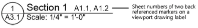
Back Ref. Sheet No. |
Indicates the sheet numbers of any markers selected for display with the Select Back References button |
|
Opens the Back References dialog box, to select objects to reference on the viewport’s drawing label. The list includes reference markers, section-elevation lines, and detail callout objects that either define the viewport (indicated by a marker in the Def column) or are linked to it, and are also within the annotations of a sheet layer viewport. Choose a category from the Back Reference list, or choose Select objects from list, and then click the Reference column of each object you want to back reference. Double-click an item in the list to temporarily highlight it and center it in the drawing window. The viewport’s drawing label must include a back reference sheet number field to display the references.
|
|
|
Layers |
Specifies which design layers are visible in the viewport and allows changes to some of the layer properties in the viewport; see Changing the layer properties of sheet layer or design layer viewports |
|
Classes |
Specifies which classes are visible in the viewport and allows changes to some of the class properties in the viewport, including changes to the properties for annotation or crop objects. Class visibilities can be overridden for a selected viewport; see Changing the class properties of sheet layer or design layer viewports. |
|
Data Visualization (sheet layer viewport) (Design Suite product required) |
Allows object attributes to be changed based on object data; see Viewing the drawing by data or by attributes |
|
Camera |
Indicates whether the viewport is linked to a Renderworks camera |
|
Background/Foreground Render |
Specifies the render mode for the viewport. Select a background mode and specify the render settings for the contents of the viewport. For a composite, sketch-like effect, creating an overlay of lines on top of the viewport, also select an optional foreground mode and specify any settings (Wireframe, Sketch, Hidden Line, or Dashed Hidden Line are the only render modes available for foreground rendering). |
|
Background/Foreground Render Settings |
Some render modes require parameters to be set; click the appropriate Render Settings button to specify them. See the following: Wireframe settings: Wireframe options Shaded settings: Shaded options Custom Renderworks settings: Custom Renderworks options Artistic Renderworks settings: Artistic Renderworks options Hidden Line, Dashed Hidden Line, and Final Shaded Polygon settings: Line render options Sketch settings: Applying sketch styles to viewports |
|
Lighting Options |
Click to change the ambient light parameters described in Setting lighting options. By default, a viewport’s ambient light is set according to the ambient light settings of the first visible design layer in the viewport. If there are no visible layers, the ambient light is set to on, with a color of white and a brightness of 35% (similar to the default ambient lighting for a design layer). If the lighting options are controlled by a Renderworks style that is currently in effect, the Edit Renderworks Style dialog box opens instead; see Renderworks styles. |
|
Advanced Properties |
Opens the Advanced Viewport Properties dialog box; see Advanced sheet layer viewport properties, Advanced design layer viewport properties, or Advanced section viewport properties. Because interior elevation viewports are technically section viewports, see Advanced section viewport properties. |
|
Reverse Direction (section viewport) (Design Suite product required) |
Switches to view the other side of the section line |
|
Section Line Instances (section viewport) (Design Suite product required) |
Lists the section line instances present in the file (see Section line instances); available for vertical sections only |
|
Navigate to Interior Elevation (interior elevation viewport) (Architect required) |
Click to view the design layer with the associated interior elevation marker and select the marker |
|
Detail Callout Instances (detail viewport) (Design Suite product required) |
Lists the detail callout instances present in the file (see Detail callout instances) |
|
Apply Image Effects (Renderworks or Shaded rendering mode and updated viewport required) |
Toggles image effects on and off |
|
Image Effects |
Opens the Image effects dialog box, for quickly and easily adjusting the viewport’s appearance |