 Creating a horizontal section viewport
|
Command |
Path |
|
Create Horizontal Section Viewport Create Section Viewport (clip cube) |
View Context menu (clip cube) |
Horizontal section viewports create a cross-section view of a model that can be customized in several different ways, as outlined in Creating section viewports.
To create a horizontal section viewport:
Prepare to create the viewport as follows:
To create a section view from a design layer, make the design layer active.
To create a section view from an existing viewport, either select a non-sectioned viewport object in Top, Bottom, Left, Right, Front, or Back view orientation, or edit the annotations of a non-sectioned viewport.
To create a section view from an existing clip cube object, use the Selection tool to highlight a horizontal face of the clip cube where the section will begin. (See Viewing a model with the clip cube.)
Select the command.
The Create Horizontal Section Viewport dialog box opens. The available parameters depend on whether you choose to place the section viewport on a sheet layer or design layer. The settings can be edited later from the Object Info palette or by right-clicking on the viewport and selecting Properties from the context menu.
The scale of a design layer section viewport is the same as the layer where it is placed. The rendering mode of the current layer is also used to render the design layer section viewport.
Click to show/hide the parameters.Click to show/hide the parameters.
|
Parameter |
Description |
|
Name viewport as Dwg No./Sheet No. (Sheet layer only) |
Select this option to automatically set the Viewport Name to be a combination of the Drawing Number and the Sheet Number assigned to this viewport. Deselect this option to enter a custom Viewport Name. |
|
Viewport Name |
If Name Viewport as Dwg No./Sheet No. is not selected, enter a descriptive name for the viewport; this name must be unique in the document |
|
Create on Layer |
Select the layer where the viewport will be created, or select New [Sheet or Design] Layer to create a layer. If there are no sheet layers present and a new one is not created now, you’ll be prompted to create a sheet layer after clicking OK. |
|
Create drawing label (Sheet layer only) |
Creates a drawing label in the annotation space of the section viewport |
|
Use style/Use default settings (Sheet layer only) |
Specifies whether the label will use a style selected from the Resource Selector or the current preferences for the Drawing Label tool |
|
Drawing Number (Sheet layer only) |
The next sequential drawing number available on the selected Sheet Layer defaults automatically. This number displays on the section marker, as well as on annotation objects in or linked to this viewport. This number must be unique on this sheet layer. |
|
Drawing Title (Sheet layer only) |
Specifies a descriptive title for the viewport, up to 63 characters. The title displays for annotation objects in the viewport. If Use Automatic Drawing Coordination is selected in document preferences, a change to this field for the viewport automatically changes the field for the viewport’s drawing label, and vice versa. |
|
Layers |
Specifies which design layers are visible in the viewport |
|
Classes |
Specifies which classes are visible in the viewport |
|
Scale (Sheet layer only) |
Specifies the viewport scale relative to the page; select a scale, or choose Custom and enter a Custom Scale value |
|
Detail Level |
Select the detail level for symbols and plug-in objects in the viewport; see Customizing detail levels for 2D and 3D components of symbol definitions and plug-in objects. Wall, slab, and roof components display at settings Medium and High. |
|
Projection (Sheet layer only) |
Select the projection type for the viewport (see Projection) |
|
Perspective Type (Sheet layer only) |
For Perspective projection, select the type of perspective, or choose Custom and specify the Perspective Dist (distance) |
|
Display planar objects |
Displays 2D planar objects; visible planar objects are sectioned if positioned at the section line |
|
Display flattened (Design layer only) |
Always displays a “flattened” section view, similar to a section viewport on a sheet layer; deselect this option to have the viewport display the current view selected for the design layer |
|
Display 2D components |
Displays 2D components (when available) for symbols and plug-in objects positioned normal to the view; see Concept: 2D components for symbol definitions and plug-in objects. When the object has no 2D component for the view, the 3D component displays. For viewports on design layers, when Display flattened is selected, the behavior is the same as for sheet layers. When Display flattened is deselected, the viewport displays 2D components only within the cut graphics. This applies only to viewports with hidden line rendering and set to a 3D view in orthogonal projection. |
|
Cut Plane |
Displays the cut plane height, which is set in the Cut Plane and Extents dialog box |
|
Relative to |
Displays to which layer, story, or story level the cut plane height is relative, which is set in the Cut Plane and Extents dialog box |
|
Cut Plane and Extents |
Opens the Cut Plane and Extents dialog box to control the height of the cut plane and the depth of the extents below and above the cut plane; see Setting horizontal section viewport cut planes and extents |
|
Display extents below cut plane |
Displays objects below the section cut plane; visible planar objects are sectioned if positioned at the section line |
|
Background/Foreground Render |
Background Render specifies the render mode for the viewport. For a composite, sketch-like effect, creating an overlay of lines on top of the viewport, also select an optional foreground mode (Wireframe, Sketch, Hidden Line, or Dashed Hidden Line are the only render modes available for foreground rendering). Some modes enable the Background/Foreground Render Settings, to specify rendering parameters. For design layer section viewports, the background render mode is set by the design layer’s setting, and Foreground Render is available only when Display flattened is selected. |
|
Background/Foreground Render Settings |
Available when the selected rendering mode requires parameters to be set. See the following: Shaded settings: Shaded options Custom Renderworks settings: Custom Renderworks options Artistic Renderworks settings: Artistic Renderworks options Hidden Line, Dashed Hidden Line, and Final Shaded Polygon settings: Line render options Sketch settings: Applying sketch styles to viewports |
|
Display 2D fills (Sheet layer only) |
When Background Render is set to Hidden Line or Dashed Hidden Line, displays 2D fills for visible planar objects below the cut plane; see Fill attributes. 2D fills also display for 2D components, when applicable. |
|
RW Background (Sheet layer only) |
Available if the Background Render mode is a Renderworks mode. If a Renderworks style is selected, but no RW Background options are available, the background is controlled by the style; see Renderworks styles. |
|
Hidden Object Display |
Opens the Hidden Object Display by Class dialog box to set the display and pen attributes for objects below the cut plane that are obscured by other objects; see Displaying 3D objects by class in section viewports. This option is available for design layer section viewports only when Display flattened is selected. |
|
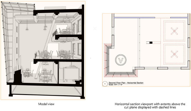
Display extents above cut plane |
Displays geometry above the cut plane. This option is available for design layer section viewports only when Display flattened is selected. |
|
Object Display |
Opens the Object Display by Class dialog box to set the display and pen attributes for objects above the cut plane; see Displaying 3D objects by class in section viewports. This option is available for design layer section viewports only when Display flattened is selected. |
|
Hidden Object Display |
Opens the Hidden Object Display by Class dialog box to set the display and pen attributes for objects above the cut plane that are obscured by other objects; see Displaying 3D objects by class in section viewports. This option is available for design layer section viewports only when Display flattened is selected. |
|
Advanced Section Properties |
Specifies advanced section viewport parameters defining the extent and attributes of the section view; see Advanced section viewport properties |
The new horizontal section viewport is displayed.
For a viewport placed on a design layer, the view is initially set to Top/Plan, but the section can be displayed in any view. A design layer section viewport can be cropped, but it does not contain an annotation space.
