 Creating interior elevation viewports
|
Command |
Path |
|
Create Interior Elevation Viewport |
View |
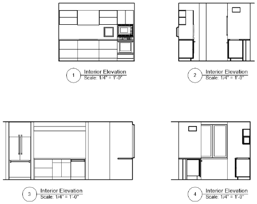
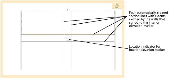
The Create Interior Elevation Viewport command creates as many as four interior elevation viewports of a room or area of a model at the same time. Interior elevation viewports are a kind of vertical section viewport, but rather than creating a cross section of the area, the command creates section lines with extents defined by the walls that surround the interior elevation marker. The drawing’s automatic coordination among the interior elevation marker and the associated viewports is maintained as long as the viewports are kept on the same sheet layer or design layer on which they are originally created.
By default, the vertical extent of the section lines is determined by the bottom of the lowest wall and the top of the highest wall of all layers visible in a sheet layer viewport, or by the height of the active layer for a design layer viewport. By default the horizontal extent is determined by the nearest walls in the XY direction of each section line; if there is no wall in a direction, the extent will be determined by the bounding box of the nearest object. Section lines, which are not visible on the design layer, can be edited after creation by clicking Edit Section Lines from the Object Info palette or by double-clicking the interior elevation marker.
To create interior elevation viewports:
Make sure the desired design layer is active (normally, this is the layer which contains the walls), and set the drawing to Top/Plan view.
Once the viewports are created, the interior elevation marker displays on the active design layer. The viewports are connected to this marker for ease of editing and automatic coordination.
Select the command.
Click once to place the interior elevation marker in the drawing, and click again to set the rotation.
The Create Interior Elevation Viewports dialog box opens to set the viewport properties.
Click to show/hide the parameters.Click to show/hide the parameters.
|
Parameter |
Description |
|
Viewport Name |
Enter a descriptive name for the viewport; this name must be unique in the document |
|
Create on Layer |
Select the sheet layer or design layer where the viewport will be created, or select New Sheet/Design Layer to create a layer |
|
Create drawing label (Sheet layer only) |
Creates a drawing label in the annotation space of each viewport |
|
Use style/Use default settings (Sheet layer only) |
Specifies whether the label will use a style selected from the Resource Selector or the current preferences for the Drawing Label tool |
|
Drawing |
Specifies the directions to create interior elevation viewports. The interior elevation marker detects its position in relation to the four quadrants in the screen plane, sweeping 45° from each XY direction (0°, 90°, 180° and 270°) corresponding to North, East, South, and West naming. |
|
Number |
For each viewport, Number defaults to the next sequential drawing number available on the selected layer. These numbers must be unique on this layer; if an existing number falls within the selected range, the number is skipped. These numbers display on the interior elevation markers, as well as on annotation objects in or linked to these viewports. |
|
Title |
For each viewport, specifies a descriptive title, up to 63 characters. The title displays for annotation objects in the viewport. If Use Automatic Drawing Coordination is selected in document preferences, a change to this field for the viewport automatically changes the field for the viewport’s drawing label, and vice versa. |
|
Layers |
Specifies which design layers are visible in the viewports |
|
Classes |
Specifies which classes are visible in the viewports |
|
Scale (Sheet layer only) |
Specifies the viewport scale relative to the page; select a scale, or choose Custom and enter a Custom Scale value |
|
Detail Level |
Select the detail level for symbols and plug-in objects in the viewport; see Customizing detail levels for 2D and 3D components of symbol definitions and plug-in objects. Wall, slab, and roof components display at settings Medium and High. |
|
Display planar objects |
Displays 2D planar objects |
|
Display flattened (Design layer only) |
Always displays a “flattened” section view, similar to a section viewport on a sheet layer; deselect this option to display the current view selected for the design layer in the viewport |
|
Display 2D components |
Displays 2D components (when available) for symbols and plug-in objects positioned normal to the view; see Concept: 2D components for symbol definitions and plug-in objects. When the object has no 2D component for the view, the 3D component displays. This applies only to viewports with hidden line rendering and set to a 3D view in orthogonal projection. For design layer interior elevation viewports, when Display flattened is deselected, the viewport displays 2D components only within the cut graphics. |
|
Display extents beyond cut plane |
Displays objects beyond the section cut plane |
|
Background Render |
Specifies the render mode for the viewport; some modes enable the Background Render Settings button, to specify rendering parameters. After the viewport is created, foreground rendering can be added for a composite rendering effect; see Viewport properties. For design layer interior elevation viewports, the rendering modes are available only when Display flattened is selected. |
|
Background Render Settings |
Available when the selected Background Render mode requires parameters to be set. See the following: Shaded settings: Shaded options Custom Renderworks settings: Custom Renderworks options Artistic Renderworks settings: Artistic Renderworks options Hidden Line, Dashed Hidden Line, and Final Shaded Polygon settings: Line render options Sketch settings: Applying sketch styles to viewports |
|
Display 2D fills (Sheet layer only) |
If Background Render is set to Hidden Line or Dashed Hidden Line, displays 2D fills for planar objects and 2D components; see Fill attributes |
|
RW Background (Sheet layer only) |
Available if the Background Render mode is a Renderworks mode. If a Renderworks style is selected, but no RW Background options are available, the background is controlled by the style; see Renderworks styles. |
|
Elevation Benchmarks (Architect or Landmark required) |
Available when the project is set up with stories. Opens the Elevation Benchmarks dialog box, to specify elevation benchmarks to link to the story levels (see Elevation benchmarks and stories). |
|
Interior Elevation Marker Settings |
|
|
Use style/Use default settings |
Specifies whether the marker will use a style selected from the Resource Selector or the current preferences for the Interior Elevation Marker tool |
|
Auto-coordinate |
Automatically displays the Drawing Number and Drawing Title of the interior elevation viewports in the marker. Deselect to enter this information manually. |
|
Drawing Number/Drawing Title/Sheet Number |
Identifies the viewports the marker references. If Auto-coordinate is deselected, enter the information manually. Otherwise, the information from the linked viewports is used. |
|
Detail Number |
Specifies a detail number for the marker |
The interior elevation marker displays on the design layer that was active when you created the viewports. It is updated to reflect which viewports were created, and to display with the selected settings. Associated viewports are placed on the specified sheet layer or design layer. Moving individual viewports to a different layer breaks the association with the interior elevation marker and the other viewports, and the relocated interior elevation viewport is converted to a section viewport.