Appearance of the planes
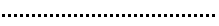
In any view other than Top/Plan, the layer plane is represented with blue rectangles. When the layer plane is the working plane, red X', green Y', and blue Z' axes are shown, and only the layer plane is shown.
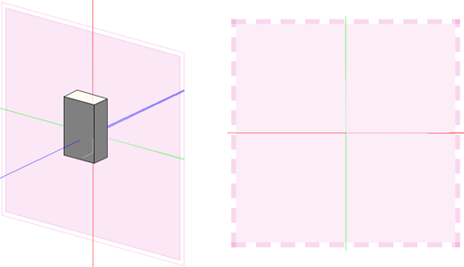
Once the position of the working plane has been changed or directly set, it is represented on the screen as a pink frame, and the X', Y', and Z' axes are rotated as appropriate; the layer plane is still visible, unless you switch to a rendered view.
In a 3D view, by default the axes are always visible, although they appear more transparent when they're behind rendered solid objects.
Layer plane as the working plane (left), and a working plane set vertical to the layer plane (right)
The color of the layer plane and appearance of the working plane can be customized in the Vectorworks preferences; see Vectorworks preferences: Interactive pane for details. Use settings in the Grid Settings popover or dialog box to show or hide the Z axis and all axis labels; see Snapping to the grid.
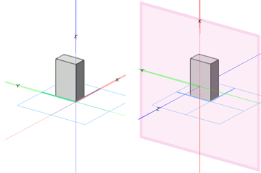
The automatic working plane is highlighted in purple when the cursor is over a suitable object. The axis lines of the working plane are red for X' and green for Y'; dashed lines represent the negative axes.
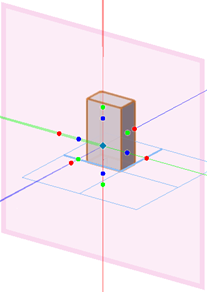
Click the border or an axis of a working plane with the Selection tool to select the working plane and display the grip handles. There are colored grips around each axis, as well as a move grip, for manipulating the plane.
The working plane displays with a double line border when viewed from behind. When the working plane is parallel to the view so that you can't see it to draw on it, the working plane displays with a dotted line border.