Creating connector panel layouts
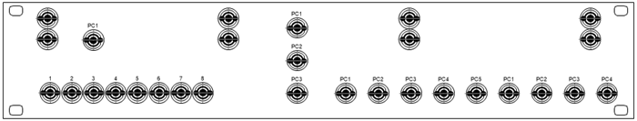
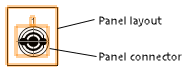
Connector panel layouts help you visualize and label standard and custom connector panels, as well as design custom panel layouts. Connector panel devices on a schematic layer are associated with the layout on a different layer. Place and label connectors in a to-scale, detailed view. When connector panels are created, they are always displayed from the front, even if they are not in a rack, to better see the panel layout.
You can create panel layouts from schematic devices, or use the Panel Builder and the Panel Connector tool to create custom panel layouts.
You can add panel connectors to panel layouts (see Placing panel connectors). When the panel layouts are complete, create connector panel devices from the layouts, and place the devices on a schematic layer (see Creating schematic devices from custom panel layouts).
Creating panel layouts from schematic devices
|
Command |
Workspace: Path |
|
Create Panel View |
Design Suite: Entertainment > ConnectCAD Documentation Spotlight: Spotlight > ConnectCAD Documentation ConnectCAD: ConnectCAD > Documentation |
This command visualizes the layout of any panels in the document. Standard rack-mount panels can use ready-made panel layout styles or be customized if necessary. Custom panels can be designed and saved as layout styles.
Panel views are created as drawing objects at actual size ready for printing or export for machining.
To create one or more connector panel layouts from the panel devices in the schematic drawing:
Select the command.
The Create Panel View dialog box opens.
Click to show/hide the parameters.Click to show/hide the parameters.
|
Parameter |
Description |
|
Search for panel-type devices in |
Creates panel layouts from selected objects, the current design layer, or all layers |
|
Select devices to create panel views |
Select which devices to include in the panel layout. A check mark in the Use column indicates that the device will be included. Click in the Layout column to open the Resource Selector and select a default resource for the device in the layout view. |
|
Select All/Deselect All |
Either select all of the devices in the list, or deselect all of the devices |
|
Select Type |
Select the type of panel devices to include in the panel layout |
|
Select Layer to use for Panel Views |
Select the design layer for the panel layout. Select New Design Layer to open the New Design Layer dialog box and either create a new design layer or import a design layer and its properties (see Creating layers). |
A layout is created for each selected panel, on the layer you specified.
A panel layout can be edited from the Object Info palette. If a style is selected, only certain parameters can be edited.
Click to show/hide the parameters.Click to show/hide the parameters.
|
Parameter |
Description |
|
Style |
Replace, edit, or remove the current style, or (for unstyled objects only) create a new plug-in style (see Custom plug-in object styles without catalog options). Editing a style changes all instances in the file that use the style. If you select a style with a graphic and panel connectors that do not match the sockets in the device, a new style displaying the selected graphic is created. To avoid creating duplicate styles, Vectorworks checks whether the new style is valid for other panel layouts that have the previously selected style. If you edit an unstyled panel layout, the panel connectors in the layout display the sockets of the selected device in the panel layout only. However, if you edit a panel layout style, the panel connectors display all sockets of that style and all sockets of that style's instances. |
|
Convert to Unstyled |
If a style is currently set, select this option to convert the object to unstyled; the current values are retained, but all parameters can be edited |
|
Hide style parameters |
Hides the parameters that are set by style; these cannot be edited from the Object Info palette |
|
Device Type |
The type of the device linked to the panel layout |
|
Device Name |
The name of the device linked to the panel layout, when there is only one |
|
Update From Schematic |
Updates the panel layout when the linked schematic devices have changed |
|
Create Schematic Devices |
Opens the Select Layer dialog box, for choosing the layer where the schematic devices created from the panel layout will be placed. This option is enabled if the panel layouts are not associated with schematic devices. Use this option, for example, when creating a custom panel layout from scratch and then creating devices on the schematic layer that are based on the layout. |
|
Panel Builder |
Opens the Panel Builder dialog box, for creating a new panel layout (see Building a panel layout with the Panel Builder). When the new panel layout is built, the contents of the selected panel layout are deleted. |
Building a panel layout with the Panel Builder
The Panel Builder provides a quick starting point for setting up a new panel. After building the layout, manual edits will be required to satisfy design requirements related to ergonomics, interference, separation of voltages, cable bend radius, etc.
To use the Panel Builder:
Select a panel layout, and then click Panel Builder from the Object Info palette.
A confirmation message asks whether you want to build a new panel, and cautions that the contents of the current panel will be deleted.
Click Yes to open the Panel Builder dialog box.
The Panel Builder dialog box opens. Build the layout by clicking Add to add connectors and to select the type, prefix, and arrangement.
Click to show/hide the parameters.Click to show/hide the parameters.
|
Parameter |
Description |
|
Connector Configuration |
|
|
Qty |
Select the number of panel connectors to create |
|
Panel Connector Symbol |
Click in the column and select a symbol from the Resource Selector |
|
Name Prefix |
Enter the prefix for the panel connectors |
|
Layout |
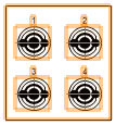
Select the layout of the panel connectors: Horizontal
Vertical
Square
Panel connectors are added to the panel layout starting from the top-left corner. |
|
Panel Type |
|
|
Create no graphics |
Creates panel connectors only, without additional graphics like mounting holes or the panel/equipment frame |
|
Rack-mount |
Select the height and rack opening for a rack-mounted panel layout |
|
Custom |
Enter custom dimensions for the panel layout and the mounting holes on the the panel layout. Select --- to create a panel layout without mounting holes. |
|
Add/Delete |
Adds panel connectors to the panel layout, or deletes the currently selected panel connector row |
|
Duplicate |
Duplicates the currently selected panel connector row, which can then be edited |


Click OK to create the custom panel layout.
If needed, double-click on the panel layout to open it in object editing mode (see Object editing mode) and rearrange the panel connectors, add connectors, and so on.
Exit object editing mode to return to the panel layout.
Creating a panel layout with the Panel Connector tool
|
Tool |
Workspace: Tool set |
|
Panel Connector
|
Design Suite and Spotlight: ConnectCAD Layout ConnectCAD: Layout |

To create a custom panel layout with the Panel Connector tool:
Click the tool, and select Single Click placement mode.
Optionally, from the Tool bar, select the Link-to Socket name, enter the Display Tag, and select a Connector symbol from the Resource Selector.
Click in the drawing to place the panel connector.
A panel layout is created with a single panel connector inside it.
Double-click on the panel layout to open it in object editing mode (see Object editing mode).
Select the panel layout, and drag a handle to expand the size of the layout.
Add panel connectors and customize them as needed (see Placing panel connectors).
Exit object editing mode to return to the panel layout.