 Circular roller chains
|
Mode |
Tool |
Workspace: Tool set |
|
Modes for The Symbol Insertion tool |
Roller Chain - Circular
|
Architect and Spotlight: Machine Components Landmark: Add tool to workspace |
Multiple roller chain tools share the same position on the tool set. Click and hold the mouse on the visible tool to open the Pop-out tools list and select the desired tool.
To insert a circular roller chain:
Click the tool and mode.
Click to place the object, and click again to set the rotation. The first time you use the tool in a file, a properties dialog box opens. Set the default parameters. The parameters can be edited later from the Object Info palette.

Click to show/hide the parameters.Click to show/hide the parameters.
|
Parameter |
Description |
|
Standard Chain No. (Pitch) |
Select the standard ANSI or ISO roller chain number; the pitch is given as a reference |
|
No. of Teeth (Sprocket) |
Enter the number of teeth on the associated sprocket |
|
Pitch Diameter (Ref.) |
Displays the pitch diameter, based on the pitch value and the number of teeth |
|
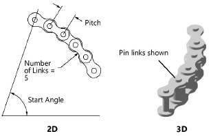
Start Angle |
Specify the angle where the chain starts |
|
Number of Links |
Enter the number of links in the chain; these will be added or subtracted from the end of the chain |
|
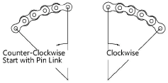
Direction |
Select Clockwise or Counterclockwise
|
|
Start with Pin Link |
Begins the chain section with a pin link; otherwise, the section begins with a roller link |
|
Show Pins (3D only) |
Draws the pins |
|
Place Locus at Center |
Draws the roller chain with a center locus
|


