Translating and rotating objects with the 3D dragger
|
Mode |
Tool |
Tool set |
|
Transform
Transform
|
Selection, Reshape
Edit Subdivision
|
Basic 3D Modeling
|


The Translate and Rotate submode provides great flexibility to complete free-form manipulations of subdivisions and some other 3D objects.
To translate and rotate an object:
Select the object to modify.
Click the tool and mode.
Click Translate and Rotate submode, and either Align to Object or Align to Working Plane mode.
As you move the cursor over the object, entities are highlighted to indicate they can be modified. Translate and Rotate submode behaves differently depending on which tool is used.
For the most part, the Selection tool uses the 3D dragger to reposition most kinds of 2D and 3D objects, not individual vertices, but there are a few special behaviors:
For most objects, the 3D dragger is positioned at the center of the object; for plug-in objects and symbols with an insertion point, the 3D dragger is positioned at the insertion point.
For objects inserted into walls, the 3D dragger is positioned to maintain the object's position in the wall. For straight walls, the 3D dragger's X axis is aligned with the wall, and for round walls, the 3D dragger is positioned at the center of the wall arc, so that using the rotational control maintains the object in the round wall.
For mesh objects, individual vertices can be selected; drag the cursor to create a marquee selection around the desired vertices.
Screen plane objects can be translated and rotated consistent with their planar orientation, but they cannot be repositioned as part of a multiple selection with non-screen plane objects. Some rotational controls are not available for screen plane objects.
Press the Ctrl key (Windows) or Option key (Mac) to duplicate and transform selected objects; a + displays near the cursor when the key is pressed.
With the Reshape tool, vertices of NURBS curves, NURBS surfaces, and 3D polygons can be moved; the adjacent edges also highlight to indicate they will change when the vertices are moved.
With the Edit Subdivision tool, the cage mesh's edges, faces, and vertices can be modified. Subdivision objects have the following additional behaviors:
Selected cage mesh entities, and the corresponding section of the subdivision model, are completely deleted from the drawing if you press the Delete key while in Transform mode; deleting a face in this way creates the open edges required for some subdivision edits. Deleted cage mesh and model faces can be restored (see Bridging open edges of a subdivision model or Closing a hole in a subdivision model). A face of the subdivision model can be removed in such a way that it can be added back to the model later (see Making a hole in a subdivision model).
To extrude multiple cage mesh faces and/or open edges as though they were a single group, hold the Alt key while manipulating the 3D dragger to activate the Extrude with Join Adjacent functionality. (An open edge is an edge with only one adjacent face; this means that the cage mesh’s other adjacent faces have been completely deleted from the drawing using the Transform mode and the Delete key.)
Click a highlighted entity to place the Translate and Rotate 3D dragger; to select multiple entities at one time, Shift-click, or Shift-drag to create a marquee selection.
The Translate and Rotate 3D dragger displays. See Repositioning the 3D dragger if needed.
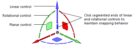
Click the 3D dragger's appropriate linear, planar, or rotational control, and move the dragger to reshape. Snapping is disabled during most 3D dragger operation; to preserve snapping for linear and rotational changes, click the segmented ends of those controls.
The selected entities are highlighted, and the active control displays in yellow during the operation. Depending on the selected control, a projection line, plane indicator, or rotation circle displays to indicate the available movement. As you move the dragger, the change previews. The 3D dragger moves differently depending on the alignment mode and dragger control selected.
Click to complete the transformation. The 3D dragger remains in place, to facilitate another reshape.
With the Selection tool, reposition one or more objects
For objects inserted in a round wall, the Selection tool's 3D dragger is positioned at the center of the wall arc, so the rotational control moves the object within the wall
A reshaped NURBS surface
A subdivision's edited cage mesh edge
A subdivision with five cage mesh faces selected, and the Alt key held for Extrude with Join Adjacent functionality