 Workflow: Model setup with stories
Depending on the complexity of the model, consider the following general workflow when setting up a Vectorworks file with stories.
Consider the project. How many floors are in the building? Is a basement needed? What type of roof are you planning to use?
Establish the known heights and the thickness of construction and assembly materials. Because stories are used, values can be easily adjusted later.
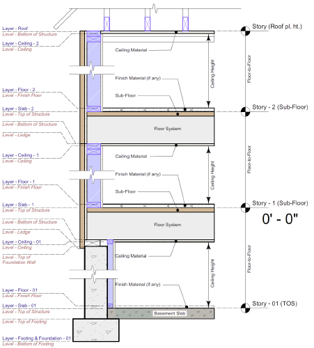
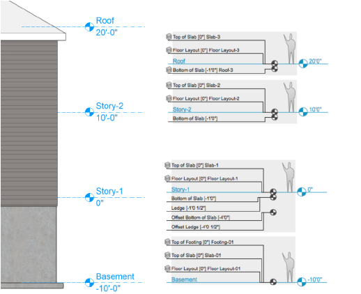
Determine the key vertical offsets. A sketch or diagram can be helpful.

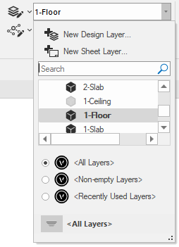
Determine the design layers to include—for example, layers for each floor's footing, basement, and floor layout; a roof layer; and a slab layer for each floor. The layers will contain all of the objects that make up the drawing, and these layers will need to be associated with stories. The layers can be created ahead of time (see Creating layers), or they can be created automatically when selecting the story levels.

Which story levels and level types will you need? Define the level types before creating default story levels. (See Default story levels.) Create any needed additional levels so that they are available from the Stories tab of the Organization dialog box. Default stories are saved in a template file, so evaluate whether you will use the same levels for other drawings and consider creating a template (see Concept: Templates).
Set the level elevations and, where appropriate, associate them with layers. Each level type can be associated with only one design layer per story, so determine which layers need to have their elevation value provided by the story to determine whether it's appropriate to assign a layer to the level type. If there are multiple design layers at the same elevation (for example 1-Floor and 1-Slab at elevation 0'0"), it's better to define the layer elevation relative to the story in the Edit Design Layers dialog box. (See Setting design layer properties.)

As described in Creating and managing stories, create the required stories and select the necessary levels and layers for each story. An example is shown below. Create a top story for the "roof" layer; its level serves as the boundary for the top wall components of the story below, and also as the elevation of the roof's bearing.

Select the wall and slab styles needed, and consider carefully how they will interact. Set the slab datum elevation, and select the wall core component, after thinking about how you will set the wall and slab component bounds in relation to these and to the story levels.
Select which levels will define the top and bottom of each wall component. Usually, the top of each wall component is bound to the bottom of the slab of the story above (this means that an extra story may be needed above the top floor; this can be a roof story). The bottom bounds for each wall component depend on whether it is an outer component bound to a ledge or to a slab, or an inner component bound to a slab, or some other atypical situation.
Select the slab datum elevation boundary and the component edge bounds. The edge bounds of the slab component affect how the slab cuts into the wall. See Concept: Stories and story-aware objects.
The model setup is complete. Draw the walls on the first floor layer, and then draw the first floor slab by picking the walls from the first floor. Repeat as you go up to the next floor layer.
When adding objects such as spaces, stairs, escalators, columns, and symbols to the layers in the model, set their boundaries according to the story levels to create a cohesive model that is structured and controlled by its building stories.
