Creating multiple viewports simultaneously
|
Command |
Path |
|
Create Multiple Viewports |
View |
The Create Multiple Viewports command generates 2D drawings from a 3D model and creates up to seven sheet layer viewports configured with several orthographic views and one isometric view of the model.
If you run the command from a sheet layer, the viewports are added to that sheet layer. If you run the command from a design layer, a new sheet layer for the viewports is created automatically.
To create as many as four interior elevation viewports of the same space simultaneously, see Creating interior elevation viewports.
To create multiple viewports simultaneously:
Select the command.
The Create Multiple Viewports dialog box opens.
Select a viewport style and/or specify the desired viewport scale, angle projection method, and views.
Click to show/hide the parameters.Click to show/hide the parameters.
|
Parameter |
Description |
|
Use Style |
To create a custom viewport, leave the Unstyled setting. To use an existing viewport style, from the Resource Selector, double-click a resource to activate it. |
|
Edit Style |
Opens the Edit Viewport Style dialog box, to edit the style (see Creating and editing viewport styles). Many viewport styles define a scale and/or view that do not permit creation of multiple viewports with this command; you can edit the style to set those parameters by instance (see Concept: Plug-in object styles). Alternatively, because editing the style modifies all objects in the file that use that style, select Create unstyled viewport from selected style below. |
|
By Style/Instance |
A graphic indicates whether each parameter that can be set by the viewport style is set to By Style and given a fixed value or set to By Instance and editable in the dialog box. A style may have a combination of both settings, to balance the need for consistency and flexibility. By Style/Instance settings are established by the style and cannot be changed from this dialog box; click Edit Style, above.
|
|
Viewport Scale |
Select the viewport scale relative to the page |
|
Method |
|
|
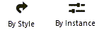
First angle projection |
Create views using the first angle projection method; by default, the front, top, and left views are selected when the drawing units are metric
|
|
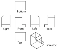
Third angle projection |
Create views using the third angle projection method; by default, the front, top, and right views are selected when the drawing units are imperial
|
|
Views |
|
|
Front, Top, Right, Left, Bottom, Back, Isometric |
Select the view(s) to create in the drawing; for the isometric view, only a right isometric or left isometric view can be created, according to the selected projection angle. If the selected viewport style sets the view by style, that view is automatically selected and these options are grayed. To create other views, you must either edit the style to set the view by instance, or create an unstyled viewport from the selected style. |
|
Create unstyled viewport from selected style |
The style's current values are retained, but all parameters are set to By Instance to allow flexibility to create multiple viewport views. |
Styled viewports, and unstyled viewports created from a selected style, are created using the style's visibility and display settings.
If no viewport style was ever selected, viewports are created using the current layer and class visibility and print area settings, with the rendered style set to hidden line rendering.
Viewports are aligned horizontally and vertically, separated by a fixed distance, and centered on the sheet layer.
Optionally, configure the viewports’ layer and class settings (Active, Show, or Gray Others only), annotate the viewport, or modify the rendering style or other viewport parameters.
For more information, see Layer or class visibility for viewports and saved views, Creating annotations for sheet layer viewports, and Viewport properties.