Creating detail viewports
|
Command |
Path |
|
Create Detail Viewport |
View Context menu |
The Create Detail Viewport command creates a cropped sheet layer viewport that shows a detail view of any part of a drawing. A detail viewport can be created from a design layer, another sheet layer viewport, or a section viewport.
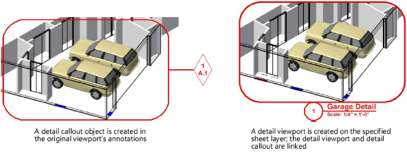
The viewport and its associated detail callout are linked, for easy navigation between layers. If the detail callout is moved or reshaped, the detail viewport updates accordingly. The detail callout marker can also be set to automatically update if the detail viewport is renumbered or moved to another layer.
To create a detail viewport:
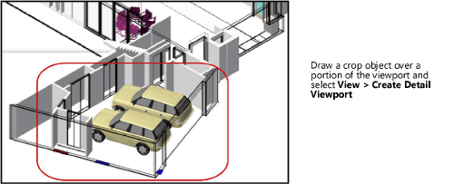
Create either a detail callout or a simple crop object (such as a circle or rectangle) on a design layer, on a sheet layer viewport, or inside a viewport annotation group. See Creating detail callouts.
Select the detail callout or crop object and then select the command.
Alternatively, right-click the detail callout and select the command from the context menu, or click Create Detail Viewport from the Object Info palette.
The Create Detail Viewport dialog box opens. Different options are available, depending on where the detail callout or crop object is located (design layer, viewport, or section viewport).
Click to show/hide the parameters.Click to show/hide the parameters.
|
Parameter |
Description |
|
Style Name |
From the Resource Selector, double-click a resource to activate it, or click Unstyled. If a styled object is converted to unstyled, the current values are retained, but all parameters are set to By Instance to allow editing. |
|
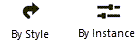
By Style/Instance |
A graphic indicates whether each parameter that can be set by the viewport style is set to By Style and given a fixed value or set to By Instance and editable in the dialog box. A style may have a combination of both settings, to balance the need for consistency and flexibility. Certain parameters must be set by instance, and are not subject to these settings. By Style/Instance settings are established by the style and cannot be changed from this dialog box.
To edit the style, see Creating and editing viewport styles; editing the style modifies all viewports in the file that use that style. |
|
General Settings |
|
|
Name viewport as Dwg No./Sheet No. |
Select this option to automatically set the Viewport Name to be a combination of the Drawing Number and the sheet layer name. Deselect this option to enter a custom Viewport Name. |
|
Viewport Name |
If Name Viewport as Dwg No./Sheet No. is not selected, enter a descriptive name for the viewport. This name displays for the viewport on the Navigation palette and Organization dialog box. The name must be unique in the document. |
|
Create on Layer |
Select the sheet layer where the viewport will be created, or select New Sheet Layer to create a sheet layer. If there are no sheet layers present and a new one is not created now, you’ll be prompted to create a sheet layer after clicking OK. |
|
Use drawing label |
Creates a drawing label in the annotation space of the viewport; select the style from the Resource Selector |
|
Drawing Number |
The next sequential drawing number available on the selected sheet layer defaults automatically. This number displays on the drawing label associated with this viewport, as well as on the detail callout. The number must be unique on this sheet layer. |
|
Drawing Title |
Specifies a descriptive title for the viewport, up to 63 characters. The title displays for annotation objects in the viewport. |
|
Layers |
Specifies which design layers are visible in the viewport; see Visibility columns. When editing viewport properties or creating/editing a viewport style, allows changes to some of the layer properties in the viewport; see Changing the layer properties of sheet layer or design layer viewports. |
|
Classes |
Specifies which classes are visible in the viewport; see Visibility columns. When editing viewport properties or creating/editing a viewport style, allows changes to some of the class properties in the viewport, including changes to the properties for annotation or crop objects. Class visibilities can be overridden for a selected viewport; see Changing the class properties of sheet layer or design layer viewports. |
|
Scale |
Specifies the viewport scale relative to the page; select a scale, or choose Custom and enter a Custom Scale value |
|
Detail Level |
Select the detail level for symbols and plug-in objects in the viewport; see Customizing detail levels for 2D and 3D components of symbol definitions and plug-in objects. Wall, slab, and roof components display at settings Medium and High. |
|
Display planar objects |
Displays 2D planar objects for all viewport view settings; when deselected, 2D planar objects display only in Top/Plan view |
|
Display extents beyond cut plane |
Available if the detail viewport is being created from a section viewport; displays objects beyond the section cut plane |
|
Display 2D components |
Displays 2D components (when available) for symbols and plug-in objects positioned normal to the view; see Concept: 2D components for symbol definitions and plug-in objects. When the object has no 2D component for the view, the 3D component displays. This applies only to viewports with hidden line rendering and set to a 3D view in orthogonal projection. If the detail viewport is being created from a design layer section viewport with Display flattened deselected, the viewport displays 2D components only within the cut graphics. |
|
Display Settings |
|
|
Background Render |
Available if the detail viewport is being created from a viewport; some modes enable the Background Render Settings button, to specify rendering parameters |
|
Background Render Settings |
Available if the detail viewport is being created from a viewport, and the selected Background Render mode requires parameters to be set. See the following: Shaded settings: Shaded options Custom Renderworks settings: Custom Renderworks options Artistic Renderworks settings: Artistic Renderworks options Hidden Line, Dashed Hidden Line, and Final Shaded Polygon settings: Line render options Sketch settings: Applying sketch styles to viewports |
|
Display 2D fills |
If Background Render is set to Hidden Line or Dashed Hidden Line, displays 2D fills for planar objects and 2D components; see Fill attributes |
|
RW Background |
Available if the detail viewport is being created from a viewport and the Background Render mode is a Renderworks mode. If a Renderworks style is selected, but no RW Background options are available, the background is controlled by the style; see Renderworks styles. |
|
Detail Callout Settings |
|
|
Detail Callout Style |
Select the style from the Resource Selector |
|
Auto-coordinate |
Uses the Drawing Number, Drawing Title, and Sheet Number from the viewport in the detail callout’s marker, and updates automatically if the viewport is renumbered or moved to another layer. Deselect to enter this information manually. |
|
Drawing Number/Drawing Title/Sheet Number |
Identifies the viewport that the detail callout marker references. If Auto-coordinate is deselected, enter the information manually. Otherwise, the information from the linked viewport is used. |
The specified sheet layer is activated, and the detail viewport is placed in the center of the sheet. If used, the original crop object is converted into a detail callout object.
Optionally, create a style resource from an unstyled object; see Creating and editing viewport styles.
You can create additional instances of the detail callout on other design layers or in the annotations of other viewports, if needed. See Detail callout instances.
To delete a detail viewport and its associated detail callouts, delete the viewport.