Concept: Creating a connected rigging system
Difficulty level: Intermediate
Braceworks calculations and, in some cases, functionality depend upon creating connected rigging systems. As rigging objects are placed in the drawing, they can automatically connect to similar objects with the same cross section. Trusses, straight trusses, curved trusses, and lighting pipes and ladders can connect to form a system. Connected to those items, hoists and loads such as lighting devices and AV equipment are also considered part of the system, and they move or adjust with the system automatically. (See Concept: Attaching loads to rigging objects for a complete list of load objects.)
Adjust the height of structural systems and all connected objects as described in Changing the trim height of a system. With this method, all items in the system move together, and the hoists’ chain lengths are automatically adjusted if needed.
Only compatible trusses can connect. If the truss to connect does not cause an existing truss to highlight, it is because they are not compatible, or one of the rigging objects does not have a valid Connectable with parameter.
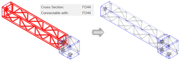
The existing truss is of the Type FD44 and can connect to otherFD44 trusses. When adding another truss, such as this corner element, the Type must also be FD44 for the system to be created.
Trusses can only connect to compatible connectors:
Spigot and connector plates can connect freely.
Gable can only connect to fork.
Spigot male can only connect to spigot female.
At insertion, gable, fork, and spigot male/female trusses flip so they connect properly. An alert opens if a connection is not possible.
When adding other objects to the drawing, such as bridles, hoists, and loads, valid rigging objects are highlighted, indicating that if placed there, the new object will connect to the system. Cables and bridles snap to the middle of a truss object. Objects like lighting devices, speakers, video screen objects, etc. snap to the chords of the truss. Copying and pasting rigging objects, and even entire systems, also uses auto connect functionality to connect to existing systems.
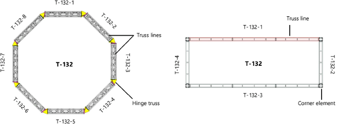
A completed truss system consists of truss lines connected with hinges or corner elements, as shown in these simple illustrations. Example naming of truss lines and the system are shown; see Renaming truss systems for more information.
The truss connection options are controlled by magnets within the truss symbol definition. Advanced users who create custom truss symbols can insert magnets automatically based on the truss record data or add them manually. See Concept: Truss magnets for more information.