Placing trusses
|
Tool |
Tool set |
|
Truss
|
Rigging/Braceworks |

The Truss tool and the Magnet tool share the same position in the Rigging/Braceworks tool set. Click and hold the mouse on the visible tool to open the Pop-out tools list and select the desired tool.
The Truss tool places a section of truss on the drawing. Depending on the resource selected, the truss may be a straight, curved (or circular), hinge, or corner element.
Hinge trusses are treated as joints in Braceworks calculations. Book hinges are assumed to be non-load-bearing structures, and center hinges are assumed to be load-bearing.
You can place one truss at a time, or place multiple straight trusses, to create a truss line. Trusses can be inserted horizontally, vertically, or at a custom hanging angle. Since you may be switching among truss modes during placement, remember the U,I,O,P,[,] shortcuts to switch modes (see Application window).
Use the Data Tag tool to add a label to the truss; see Adding data tags and labels.
|
Mode |
Description |
|
Truss Symbol |
Select the truss to insert |
|
Change Insertion Point
|
While connecting a truss to an existing truss, click to change the insertion point of the inserted truss to the next magnet |
|
Single Insertion
|
Inserts a single truss object |
|
Distributed Insertion
(straight truss only) |
Inserts multiple truss objects in a row |
|
Horizontal Placement
|
Places horizontal trusses; the hanging angle is 0 (zero) degrees |
|
Vertical Placement
|
Places vertical trusses; the hanging angle is 90 degrees |
|
Custom Placement
|
Places trusses at the specified Hanging Angle |
|
Hanging Angle |
Specify the hanging angle for Custom Placement |
|
Automatic Numbering
|
When toggled on, enables automatic numbering as objects are placed |
|
Automatic Numbering Preferences
|
Sets the automatic numbering preferences |


A truss object whose symbol definition cannot be located will display with default geometry, until a replacement symbol is assigned.
Placing a truss object
You can start a new truss system by placing one or more truss objects.
To place a truss or truss line:
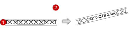
Click the tool, and then click Truss symbol on the Tool bar to select a resource from the Resource Selector. If the selected symbol has insufficient data for proper calculations, the Truss Properties dialog box opens; see Setting custom truss parameters.
If a truss symbol is accidentally inserted by the Symbol Insertion tool, the truss functionality will not be present. When correctly inserted, the Object Info palette displays “Truss” for the selected truss.
Click the insertion mode. Distributed Insertion mode only applies to straight trusses.
Change Insertion Point mode only applies while adding trusses to an existing truss.
Click the placement sub mode, to determine the hanging angle. A 3D view is recommended when placing distributed vertical trusses. If Custom Placement is selected, specify the Hanging Angle.
Click once to set the truss insertion point.
Do one of the following:
In Single Insertion mode, move the mouse to orient the truss, and click again to place it. For a hinge truss, click a third time to set the truss angle.
In Distributed Insertion mode, click to place the first truss. Move the mouse to orient and place the trusses along a line; trusses are placed end-to-end, and the preview indicates how many trusses will be placed. Click again to place trusses along the full length of the line. If the line length is not an exact multiple of the selected truss length, an additional truss is added to complete the line, resulting in a longer truss line.
Adding a truss in Single Insertion mode in Top/Plan view
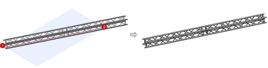
Adding a truss in Distributed Insertion mode in a 3D view
Hinge trusses are placed similarly and can only be placed in Single Insertion mode. After placement, select the hinge and adjust the hinge angle with the handles (or edit the Hinge Angle on the Object Info palette). The hinge angle must be between the Minimum and Maximum Angle specified in the Truss Properties dialog box; if not, the closest valid angle will be used.
Adjusting the hinge angle after placement (2D and 3D views)
The parameters can be edited later from the Object Info palette (see Truss properties).
Connecting trusses to form a system
When you add a truss to another truss or a truss line, it is automatically inserted at the same hanging angle as the existing system, even if a different placement mode or hanging angle is specified. Depending on the resource selected, the added truss may be a straight, curved (or circular), hinge, or corner element.
To create a valid truss system, place truss symbols that are compatible with the existing trusses (same manufacturer and type of truss).
You can also drag an existing truss to a desired connection point on the system, or copy an existing truss and add the copied truss to a system, by pressing Ctrl (Windows) or Option (Mac) while click-dragging.
To add trusses to an existing system:
Click the tool and modes, and select the truss symbol, as described in the section above.
Move the mouse to hover over an existing truss; valid connections are highlighted.
Depending on the type of truss to connect and the view, various insertion options are previewed. For example, connecting a three-way corner truss shows different options from connecting a four-way truss, and connecting a book hinge shows different options from connecting a center hinge. For all trusses, Top/Plan view provides different options from 3D insertion.
Connecting to a vertical truss depends on the current view. In Top/Plan view, trusses can only be added to the top end of an existing truss; in 3D views, trusses can be added to the top or bottom end.
Connecting trusses at a custom hanging angle also depends on the current view. For best results, set a view that is perpendicular to the truss direction, and use Orthogonal projection.
If no highlighting occurs, there may be a connection already in place, or the trusses may not be compatible connectors.
When the desired location is highlighted, do one of the following to insert the truss:
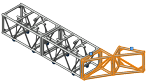
If you are placing more of the same type of trusses in Single Insertion or mode Distributed Insertion mode, click at the highlighted location (where truss magnet snapping occurs) to place the new truss, connected to the system.
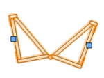
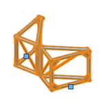
If you are placing a corner or hinge truss, click once to place the truss element at the highlighted location (where truss magnet snapping occurs). In a 3D view, the working plane appears, with a red guide line; move the mouse to view the possible orientations for the truss element, and click when you have the correct orientation. For a hinge, click one more time to specify the hinge angle. In Top/Plan view, you cannot see the working plane or the guide line.
If you are having trouble connecting to the system with the desired orientation, especially in Top/Plan view, click Change Insertion Point mode (which acts as a button, rather than a mode). This changes the insertion point of the inserted truss to the next magnet. In Top/Plan view, clicking the button switches between 2D magnets, and in a 3D view, it switches among 2D and 3D magnets.
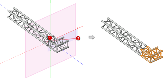
When connecting to an existing truss, click to connect, move the mouse to orient (or click Change Insertion Point mode), and click to place
After placement, adjust the hinge angle with the handles or from the Object Info palette. The hinge angle must be between the Minimum and Maximum Angle specified in the Truss Properties dialog box; if not, the closest valid angle will be used.
The parameters can be edited later from the Object Info palette (see Truss properties).