Multi cable connections
|
Mode |
Tool |
Workspace: Tool set |
|
Distributor
Schematic Distributor
|
Cable
|
Design Suite, Spotlight: Cable/Power Planning ConnectCAD: Cable Route |


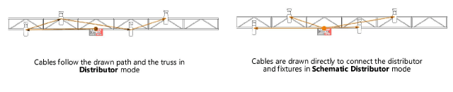
Distributor and Schematic Distributor modes both connect distributors to electrical devices. The first mode patches electrical devices to a distributor by creating cables that follow a drawn path. The second mode also connects distributors and electrical devices, but it draws the connection as a direct link, to clearly identify the devices plugged into the distributor. To automatically insert specific twofer symbols and parameter settings based on the cable connection type, specify the default twofer distributor to add in the Twofer Options pane of the Cable Preferences (see Setting cable preferences).
In both modes, pressing the Ctrl key (Windows) or Option key (Mac) while clicking on an electrical device connects the device to the same circuit as the previous device, creating a daisy chain connection. Holding down the key while clicking on devices continues to create a daisy chain on the same circuit. If a twofer is inserted, pressing Ctrl or Option while clicking on lighting devices connects the devices to the same circuit without creating a daisy chain. Releasing the key terminates the circuit.
The number of electrical devices that can be connected is equal to the number of outputs on the distributor. If there are more devices than available distributor outputs, then more than one twofer distributor is inserted.
If you try to daisy chain lighting devices that do not have outputs, the Cable Preferences dialog box opens with the Twofer Options pane displayed. You can select a twofer symbol to insert or use another circuit for the lighting device (see Setting cable preferences).
To connect a distributor to multiple electrical devices:
Click the tool and mode.
If desired, click Cable Style on the Tool bar to select a resource from the Resource Selector.
Click the appropriate mode in the Tool bar to select the creation method for the cable. For more information on the polyline tool modes, see Creating polylines.
Click on the source distributor; the first click must be on a distributor object with outputs. The Select Distributor Output dialog box opens. See Selecting the output. (If the option to select the next free output is selected, the dialog box does not open.)
Do one of the following:
In Distributor mode, if a cable path exists, the cable will snap to it. If the option to Automatically follow paths when a cable is drawn is selected in the Cable Preferences, the cable follows existing truss system and cable paths to make the connection. The new cable can use all or part of the path. Click on the path at the desired entry point. The cable will exit the path at the end of the cable path closest to the next click; continue clicking to complete the cable run.
To exit the cable path before the end of the path, press the Alt key (Windows) or Option key (Mac) while drawing the cable.
In Distributor mode, if not using a cable path, click on a blank space to set a path for the cable to follow on its way to the devices it connects to. Set the end of the segment and the beginning of the next, snapping to existing geometry. As you place the cable, compatible objects such as distributors, electrical devices, other cables, and trusses are highlighted; click to connect. If the option to Automatically follow paths when a cable is drawn is selected in the Cable Preferences, the cable follows the existing truss system to make the connection. Continue drawing segments in this manner and double-click when the cable is complete.
Schematic Distributor mode does not make use of a cable path, since it's a schematic depiction. Click on the first device to connect to, and then continue to click on the remaining devices to connect.
In Distributor or Schematic Distributor mode, press the Ctrl key (Windows) or Option key (Mac) while clicking on an electrical device to connect the device to the same circuit as the previous device, creating a daisy chain connection. Hold down the key while clicking on devices to continue creating a daisy chain on the same circuit. If a twofer is inserted, press Ctrl or Option while clicking on lighting devices to connect the devices to the same circuit without creating a daisy chain. Release the key to terminate the circuit.
A cable connects each output from the distributor to the electrical device, either following the path drawn in Distributor mode, or with a direct path in Schematic Distributor mode. Depending on the Cable Preferences, the connector cables can appear curved for easy identification.