Editing cables
Reshaping cables
|
Tool |
Tool set |
|
Reshape
|
Basic |

Reshape a cable run path by double-clicking on it, or by right-clicking on it and selecting Edit Path from the context menu. The Reshape tool is automatically activated to reshape the object. You can also add cable breaks to split a cable into several sections.
The available Reshape tool sub-modes are similar to those for the NURBS curve (see Reshaping NURBS curves), with additional modes for the Reshape Path, Edit Breaks, and Move Break modes.
|
Mode |
Description |
|
Reshape Path
|
Reshapes the cable run section; you can move, add, delete, or change the vertices of the cable. If one of the end points of the cable is moved, the cable will search for devices or distributors to connect to at the new location of the end point, if the other end is also connected. Highlighting indicates where you can can associate with new devices or distributors. If you move the cable vertex, adding to its length, cable length parameters adjust. You can change the vertex type, for example, to create a smooth path to illustrate swag. |
|
Edit Breaks
|
Splits an existing cable into multiple cable parts. Combine the mode with the Add Vertex submode to split (break) cables in a specific spot, allowing control over the location of connectors in the cable run. For example, you might need to note a cable break for a door that must be allowed to open and close, or a truss that has to move into position at a different time from another truss. Split cables share the same Cable Run ID and connections. Combine the mode with the Delete Vertex submode to delete existing cable breaks. The previously separate sections are combined into one, using the start slack of the start section and end slack of the end section. This section's cable parts are rebuilt. |
|
Move Break
|
Moves existing cable breaks. Only the cable sections at the cable break have their cable parts rebuilt, ensuring that there is enough cable length for each section. |


After reshaping, the cable run parts are rebuilt using the correct number of parts based on the inventory and new cable length, and the connections update.
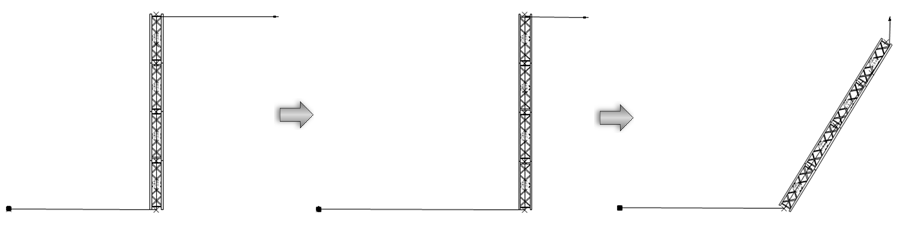
A cable run automatically adapts when the cable path it follows is reshaped, or when the cable path or truss system path is moved or rotated.
The Reshape tool only acts on one cable at a time. If you need to add a cable break to several selected cables at a common point, right-click on the selected cables and select Add Cable Break Point from the context menu.
Edit cable break properties by double-clicking on the cable break (if there are several cable breaks at the same location, all cable breaks at that point are edited). The Edit Cable Break(s) popover opens. Enter the name of the cable break, which is used in reports and data tags. You can also specify slack lengths for the cable sections at the start and/or end of the break; enter the slack cable lengths, which are added to the cable length for reports and calculations.
Cable settings
The cable appearance can also be edited by clicking Settings from the Object Info palette.
When using a cable style, the cable appearance, type, connectors, class settings, and data tags are preset. The settings can be adjusted if needed, and a new cable style resource can be created.
To change the cable settings:
From the Object Info palette of a selected cable run, click Settings.
The Edit Cable Settings dialog box opens.
Click to show/hide the parameters.Click to show/hide the parameters.
|
Parameter |
Description |
|
Use Style |
From the Resource Selector, double-click a cable style to apply it. See Concept: Plug-in object styles. |
|
Convert to Unstyled |
Converts a styled cable to unstyled for editing; the current values are retained, but all parameters on all panes are set to By Instance to allow editing |
|
General |
|
|
Tape Color Code |
Identifies the cable with a color code, which can be used to label racks and breaks |
|
Start Connector/ End Connector |
Specifies the connector at either end of the cable |
|
Cable Type |
Select one of the cable types |
|
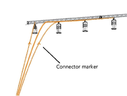
Connector Marker |
Select a marker to indicate where connectors are located along the cable run
|
|
2D Visualization |
|
|
Line Style |
Select a line type and thickness for the cable |
|
Line Start Marker/Line End Marker |
Specify a starting and ending marker for the cable |
|
Label Fill |
Select whether the cable label text should have a solid fill or no fill; the fill color is set by the class on the Classes pane |
|
Classes |
To control appearance and visibility of the various labels and portions of the cable, select a class from the list of classes present in the drawing, or create a new class |
|
Data Tags |
|
|
Data Tags list |
Displays the data tags that will attach to the cable at insertion, and where they will be inserted; see Adding data tags and labels. Click the Add button to populate the list. Then select a data tag from the list and set the parameters. |
|
Add |
Adds a data tag to the list |
|
Delete |
Removes the selected data tag from the list |
|
By Style |
Select whether the symbol properties are set by style or by instance |
|
Data Tag Symbol |
Click the Resource Selector to select a data tag symbol. Navigate to the Entertainment folder and select the Cable Distributor file to display the data tags for cables. |
|
Position |
Select where to position the data tag: at the start, mid-point, or end of the cable run, or at the start of each cable part in the cable run. When placing a data tag at the start of the cable run, if you want the tag to include the name of the first cable in the run, add the UsedPartsOrdered field to the data tag definition; see Editing data tags. |
|
Offset |
Specify the distance to offset the data tag from the cable |
|
Rotate with cable |
Rotates the data tag to match the angle of the closest cable part |
|
Class |
To control appearance and visibility, select a class from the list of classes present in the drawing, or create a new class. Select <Object Class> to place the data tag in the same class as the cable object. Select <Data Tag Style Default Class> to use the class specified for the data tag's style. |
Optionally, create a style resource from the object (see Creating plug-in object styles).
Cable objects can be directly edited from the Object Info palette. For cables using object styles, the parameters that are set by style display for informational purposes and cannot be edited. Many of the Object Info palette parameters are for informational and reporting purposes.
Click to show/hide the parameters.Click to show/hide the parameters.
|
Parameter |
Description |
|
Style |
Replace, remove, or edit the current style, or create a new plug-in object style for this object; see Changing plug-in object styles from the Object Info palette. Editing a style changes all instances in the file that use the style. |
|
Hide style parameters |
Hides the parameters that are set by style; these cannot be edited from the dialog box or Object Info palette |
|
Settings |
Opens the Cable Settings dialog box, to specify the type, connection, and appearance of the cable; see Cable settings |
|
Cable Type |
Displays the type of cable (feeder, data, jumper, or multi) |
|
Cable Run ID |
Names the cable run, which is useful for labels, schedules, and other worksheets. This ID can also be used by ConnectCAD circuits to associate the cable with a circuit (ConnectCAD required). In ConnectCAD, the shortest route through the network is assigned by default. Using a Spotlight cable object and assigning it to the circuit in question overrides this; the length and routing of the cable object is used instead of the automatically calculated route. |
|
Universe |
Indicates the universe assigned to the cable |
|
Rack ID |
Names the rack to which the cable connects |
|
Box ID |
Provides the distribution box name |
|
Port ID |
Names the port where the cable plugs in |
|
Loom ID |
Names the loom or bundle that includes the cable |
|
Tape Color Code |
Identifies the cable with a color code, which can be used to label racks and breaks |
|
Start/End |
Displays the connected object (distributor, electrical device) at the start and end of the cable |
|
Adapter Start/End |
If an adapter is present at the start or end of the cable, select it from the list. Enter text in the search box to filter the list. |
|
Location |
Specifies the cable location |
|
Volt |
Specifies the cable voltage provided by the power source |
|
Ampere |
Specifies the maximum amperage for the power source |
|
Length |
Displays the total length of the cable run |
|
Cable Configuration |
Opens the Cable Configuration dialog box, to specifically define the cable portions that make up the cable run; see Cable run configuration |
|
User Field 1/2/3 |
Adds optional notes or comments about the cable, useful for reporting purposes. Field 3 is for entering a number only. |
|
Voltage Drop |
Displays the amount of voltage lost to cable resistance |
|
Start Connector/End Connector |
Specifies the connector at either end of the cable; select a different connector if needed |
|
Select by Length |
Selects all cables with the same length as that of the currently selected cable; this quickly identifies where the cable is used in the drawing for editing or other purposes |
|
Load Information |
A cable is considered a load in Braceworks calculations; if the insertion point is on a structural element, it is considered to be a load on that structure. Load information is used for Braceworks calculations and reports (Braceworks required). |
|
Include in calculations (Braceworks required) |
Includes the cable in Braceworks calculations; deselect to exclude the object from participating in structural calculations |
|
Load Group Name |
The load category is always Cable |
|
Load ID |
Enter a unique ID for the load for informational use in reports |
|
Load Name |
Identifies the object in load calculations; normally the object name is used |
|
Distributed Weight |
Specifies the distributed weight of the cable; changes here affect the Total Weight value |
|
Total Weight |
Enter the total weight of the object |
|
Position |
Displays the name of the associated rigging object, if the cable is attached. For methods to attach loads, see Making the attachment. |
|
Equipment Subparts |
Lists the subparts that make up the object. These subparts are counted and reported separately in equipment and inventory lists. The parameters must be selected for display for this type of object in Spotlight preferences: Inventory pane. |
|
Equipment Virtual Parts |
Virtual parts are associated with an object and are reported in equipment and inventory lists, but do not display in the drawing. After adding virtual parts, they are listed in the Object Info palette. |
|
Edit Virtual Parts |
Opens the Virtual Parts dialog box to add virtual parts to the object; see Managing virtual parts and independent virtual parts |
|
Assign Sources |
Opens the Assign Sources dialog box to assign the object and its subparts and virtual parts to an inventory source; see Assigning equipment to an inventory |
Cable run configuration
A cable run is made up of cable parts of specific types and lengths. The configuration of one or more cable runs can be adjusted if needed. Cable sections include the following data: name, start slack, swag, end slack, and cable parts. The slack and swag lengths contribute to the total needed length of the cable section, which also affects how many cable parts will be needed for this cable section. All of this data can be displayed in data tags and reported in worksheets, and most of the data can be edited from the worksheets.
To change the cable run or cable section configuration:
From the Object Info palette of a selected cable run, click Cable Configuration.
The Cable Configuration dialog box opens.
If multiple cables are selected, a Cables list on the left allows you to select which cable to edit, or to edit <All cables>.
If the cable run was broken into sections, using the Edit Breaks mode of the Reshape tool, a Sections list on the left allows you to select which section of the cable to edit, or to edit <All sections>.
Click to show/hide the parameters.Click to show/hide the parameters.
|
Parameter |
Description |
|
Parts |
Select the cable parts for the cable run or the cables selected from the Cables list |
|
Available Parts |
Lists the available cable parts |
|
Search |
Enter text in the search box to filter the list |
|
Only show compatible parts |
Filters the list of available parts to show only the compatible parts (these have the same start and end connectors as the selected cable run) |
|
Manage Cable Parts |
Opens the Manage Cable Parts dialog box, for determining the cable parts that are available for use; see Managing cable parts |
|
> |
Adds a selected cable part (or parts) from the available parts list to the selected parts list; alternatively, double click to move the parts |
|
< |
Removes the selected cable part (or parts) from the configuration; alternatively, double click to move the parts |
|
Selected Parts |
Lists the cable parts for the cable run |
|
Combined Parts Length |
Reports the total length of the cables listed in Selected Parts; this value updates as the list changes |
|
Summarize parts list |
Lists the parts according to type, showing the quantities of each type of cable part |
|
List all parts |
Lists each cable part in the configuration in order. Drag and drop to rearrange the order. |
|
Cable Information |
Displays information about the cable run or cables, and how the length of the cable run was calculated. Drawn Length: Total length of the path that represents the cable in the drawing. Specified Spare: Length of the spare cable (from Cable Preferences). Specified Swag: Length of the cable swag (from Cable Preferences). Circuit Output Length: Length of the circuit tail of break out distributors connected to the cable run. Total Needed Length: Total length of the cable run required in the drawing, calculated by adding up the drawn length, spare, swag, and circuit output length. Cable Run Overage: Subtracts the Total Needed Length from the Combined Parts Length to confirm that sufficient cable has been assigned to the run. Voltage Drop: Percentage of voltage lost to cable resistance. |
|
Sections |
Cable runs may be broken into sections, using the Edit Breaks mode of the Reshape tool. This tab lists the sections that make up the cable run, allowing you to name selected sections, and/or add slack to the start or end of the section. If <All sections> is selected, the slack is added to the start and/or end of the entire cable run. Click Reset to Default Swag to remove any swag changes that were made to sections. |
The Cable Information area displays cable information including the Total Needed Length, which is compared to the Combined Parts Length. Locate the needed available cable parts and move them to the Selected Parts list to construct the cable run configuration, ensuring that it is at least as long as the Total Needed Length. Use the < and > buttons, or simply drag and drop the cable parts between the lists.
If the cable configuration has issues, an alert opens when you close the dialog box. Situations that prompt an alert include a cable run which is too short, or too long (with shortening possible), or has sections which are too long and sections which are too short.
Do one of the following:
Click Rebuild Sections to rebuild all the sections with issues using the Default Parts settings from the Cable Preferences dialog box. The Cable Configuration dialog box reopens, displaying the first rebuilt section.
Click Cancel to reopen the Cable Configuration dialog box. The first section with cable issues is displayed so you can manually add or subtract parts.
If needed, adjust the cables that are in the available parts list by clicking Manage Cable Parts. Review the cable inventory and make any required changes.
Cable errors
If connection errors occur during placement, the Cable Errors dialog box opens, listing the problems and the affected connections. A different distributor, cable style, or connector may be needed, or an adapter may be required. To avoid future connection errors, select Automatically use adapters for future connection errors. This will add adapters to affected connections, ensuring that the appropriate connections can be made, and the errors dialog box will no longer open.