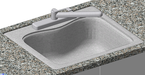
 Countertop insertions
A symbol, such as a sink, can be used to cut a hole into the countertop. When the object is inserted, an association is created between the inserted object and the countertop, so that if the insert is moved, the hole in the countertop moves, too.
In order to be inserted into a countertop and create its own hole, a symbol definition should have the insertion point at zero, the symbol definition must have the Insert in Walls option enabled, and it must have a hole component (see Creating symbol definitions and Adding a hole component to a symbol definition).

Inserting symbols into countertops
To insert a symbol into the countertop:
Do one of the following:
Click the Symbol Insertion tool in the Basic palette, and then click Active Symbol Def on the Tool bar to select a resource from the Resource Selector.
From the Resource Manager, right-click on the resource, and select Make Active from the context menu. Alternatively, double-click the resource to activate it.
From the Resource Manager, drag the symbol to the desired location in the drawing. Select the appropriate folder in the Import Resources dialog box to activate the symbol.
The symbol must be present in the active file in order to associate the symbol with the countertop. In addition, ensure the Symbol Insertion tool's Standard Insertion mode is active to insert a symbol into a countertop.
As you move the cursor over the countertop, it highlights to show the object's association. Click to place the insert, and click again to set the rotation. The symbol automatically cuts the hole.
Note that not all sinks can be associated and inserted into countertops, such as pedestal sinks. The cabinets underneath are also not associated with the symbol insertion.
Inserting symbols into countertops by fitting to cabinets
You may want to place symbols in countertops with even more precision. In such cases, symbols can be placed to fit the cabinets created below the countertop, and then associated with the countertop.
To insert a symbol into the countertop by fitting to cabinets:
Before creating the countertop (or with the countertop hidden), place the symbol(s) in the desired position relative to the cabinets.
Draw the countertop on the cabinets (or unhide the countertop).
With the countertop selected, click Pick Symbols to Associate from the Object Info palette; alternatively, right-click the countertop, and then select Pick Symbols to Associate from the context menu.
Select the symbol(s) to associate with the countertop, and then double-click to associate them or click the green check mark on the Tool bar.
Editing countertop insertions
Insertions can also be edited from the Insertions dialog box once they are created.
To edit insertions:
Click Insertions from the Object Info palette, or right-click on the countertop and select Edit Insertions from the context menu.
The Insertions dialog box opens. When this dialog box is accessed through the Object Info palette or a context menu, the view in the drawing area changes to a Top/Plan view, and the selected insertion is highlighted.
Alternatively, click Countertop Settings in the Object Info palette, and then click the Insertions pane. When insertions options are accessed this way, the view doesn't change and the selected insertion is not highlighted.
Select the insertions to edit in the list browser.
Click to show/hide the parameters.Click to show/hide the parameters.
|
Parameter |
Description |
|
Insertions list |
Lists all the inserted objects and holes made directly or via symbol. Select a row to edit the symbol or edge treatment using the options below. Select Undermount to move the insert below the countertop. |
|
Inserted Symbol |
Displays the inserted symbol; select to replace the symbol |
|
Hole Edge Treatment |
If desired, select to set the 2D profile for the (symbol) hole or edit a previously set edge treatment |
|
Delete Insertion |
Deletes the symbol from the countertop |
After a symbol has been placed, the 3D hole component can still be edited. Edge profiles can be added to holes that are made using 2D polylines. You can also use 2D polylines along with the 3D geometry for hole cutting to create custom objects such as a drainage board. See Adding a hole component to a symbol definition.
