Adding a hole component to a symbol definition
By adding a hole component to a symbol definition, the symbol has the ability to cut holes of a wall, slab, or countertop. The geometry drawn to define the shape of the hole can consist of any solid shape or shapes. If a 3D hole component is included in a symbol definition, any existing 3D loci in the 3D component of the symbol are ignored. 3D geometry must be used to cut holes in walls and slabs. 3D geometry can also be used to cut holes in countertops; however, 2D shapes can also be used with the advantage of having edge profiles applied to them.
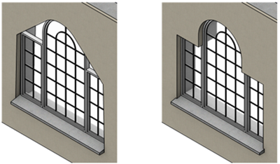
If the symbol has no hole component (shown on the left), the wall creates an opening that fully encompasses the 3D shape. With a hole component (shown on the right), the symbol creates a hole of the proper shape.
When wall closure settings are used, you may need to add a wall closure component to achieve the desired effect. If wall closure wrapping is set to Wrap to Insert in the Wall Closures at Inserts dialog box or Wall Closure dialog box for any component, the wall closure component provides the geometry for wrapping. See Adding a wall closure component to a symbol definition and Wall closure settings.
To add a hole component to a symbol definition:
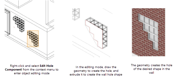
Right-click a black symbol instance from the drawing, and select Edit Hole Component from the context menu to enter object editing mode (see Object editing mode).
Other drawing objects display, and can be snapped to, while in the editing mode (the Vectorworks display preference Show other objects while in editing modes must be enabled). The symbol being edited displays with its pen style attributes, to distinguish it from the rest of the drawing.
Alternatively, right-click on the symbol definition in the Resource Manager to enter the editing mode without the display of other drawing objects; see Editing symbol definitions.
Any shape can be drawn to define the hole shape. The geometry must intersect the wall, slab, or countertop. There are a few methods for drawing a hole component based on the type of geometry:
To create a 3D hole component, create and extrude a 3D hole shape. Alternatively, create 3D hole geometry directly using 3D modeling tools. By default, hole geometry is created using a red pen color; this can be changed from the Attributes palette if desired.
To create a 2D hole component, create a 2D planar object the right size and shape, then trace the symbol outline to define the hole shape.
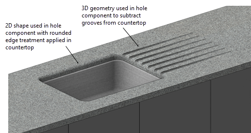
For a countertop with a sink and custom drainage board, a hole component using a combination of 3D and 2D geometry can be used
When the hole is used in conjunction with a profile/wrapping wall closure, part of the wall geometry might need to be excluded from the wall. For example, you may be creating a lintel or sill. In this situation, draw a 3D object to represent the part of the hole to exclude from the closure. Select that object, and select Ignore closure on the Object Info palette. This results in that geometry being subtracted from the wall after the closure has been applied.
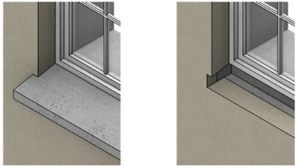
Add a 3D object to the hole component the same shape as the sill, and select Ignore closure to delete that geometry from the wall after the wall closure is applied (sill object hidden to show the effect on the wall)
Exit object editing mode to return to the design layer.
Since the hole component was added to the symbol definition, all instances of the symbol will cut holes in surfaces according to the geometry drawn.
Applying textures to 3D wall hole components
Special texture parts for wall hole components can be applied from the Object Info palette. See Managing object textures from the Object Info palette and Textures on objects with components. While editing the 3D wall hole component, the Assign Part list on the Render tab of the Object Info palette lists three options for the different textures that can be applied to wall hole faces: Holes, Wall Left, and Wall Right.
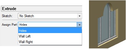
|
Texture part |
Result |
|
Holes |
Applies the texture specified for the wall’s "Holes" part to the wall faces created by the cutting object |
|
Wall Left |
Applies the texture specified for the wall’s "Left" part to the wall faces created by the cutting object |
|
Wall Right |
Applies the texture specified for the wall’s "Right" part to the wall faces created by the cutting object |
Each 3D hole component can only have one texture part defined. Therefore, up to three different cutting objects would be necessary to apply three different texture parts to the hole faces.