 Placing drip outlets
|
Tool |
Tool set |
|
Drip Outlet
|
Irrigation |
The Drip Outlet tool places an irrigation drip outlet—linear drip lines, or rows of drip lines within a defined area, which allow water to seep out. (This is different from the drip tubing type of the pipe object, which does not leak water; it transfers the water to drip emitters along its length.) The parameters for the drip outlet come from a selected manufacturer or can be placed as a custom drip outlet with parameters that can be specified after placement.
A drip outlet added to a pipe splits the existing pipe in two.
|
Mode |
Description |
|
Standard Insertion
|
Inserts a drip outlet according to the selected placement mode |
|
Pick Up
|
Sets the default drip outlet settings to match those of a selected existing drip outlet; see Transferring outlet attributes |
|
Convert
|
Places drip outlets over a valid irrigation object (pipe or polyline) by clicking on it; see Transferring outlet attributes |
|
Outlet |
Opens the Resource Selector to select a drip outlet resource for placement; double-click a resource to select it. Select from one of the manufacturer libraries, or select the custom drip outlet from Custom.vwx and set its properties after placement. |
|
Drip Line
|
Creates a drip line along the drawn polyline |
|
Drip Area
|
Creates an area with rows of drip lines |
|
Polyline creation options |
Selects the method for drawing the polyline upon which the object is based; see Creating polylines |
|
Preferences
|
Sets the default preferences for the drip outlet object |
To place drip outlets on the drawing:
Click the tool and then click Standard Insertion mode from the Tool bar.
Click Outlet on the Tool bar to select a resource from the Resource Selector. Select from one of the manufacturer libraries, or select an outlet closest to the type you need from Custom.vwx and set its properties after placement.
Alternatively, create a closed 2D shape and then select the Create Objects from Shapes command to create a drip outlet (see Creating objects from shapes).
Click the placement mode from the Tool bar.
Click Preferences to open the object properties dialog box and specify the tool’s default parameters for placement and appearance. The Drip Outlet tool uses these preferences until they are changed again, or until Pick Up mode is selected, which changes the settings to those of a selected existing drip outlet. Many of the parameters can be edited later from the Object Info palette.
Click to show/hide the parameters.Click to show/hide the parameters.
|
Parameter |
Description |
|
Drip Outlet Name |
Names the object, which is useful for labels, irrigation schedules, and other worksheets |
|
Note |
Adds a note about the object, which is useful for labels, irrigation schedules, and other worksheets, and also for making notes when saving red symbol definitions |
|
Use Default Trench Depth |
Uses the default trench depth specified in the irrigation settings; deselect to enter the trench depth manually |
|
Trench Depth |
Displays the default trench depth, for informational purposes; when Use Default Trench Depth is deselected, enter the trench depth |
|
Graphics |
|
|
Show Pressure |
Places a pressure label on the drawing |
|
Show Flow |
Places a flow rate label on the drawing |
Click once to set the drip outlet location. If placing the drip outlet over an existing pipe or irrigation pipe network, the connecting pipe is highlighted and the drip outlet is automatically connected to the network.
For drip outlets placed in Drip Line mode, draw the drip line polyline, clicking at each vertex. Double-click to finish drawing the drip line. Only the start end of a drip line can be connected to an existing pipe.
For drip outlets placed in Drip Area mode, draw the outline of the drip line area, clicking at each vertex. Double-click to finish drawing the drip line area.

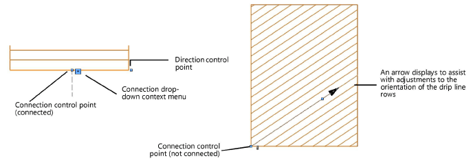
Placing a drip line (left) and drip area (right)
Adjust the position of any pressure and flow labels by dragging the label control point.

Adjust the orientation of the drip line rows in a drip area by dragging its control point. The connection point also has a control point; when the drip line area is not connected to a network, the connection point is indicated by a chain link image.

For a different style of drip area display, deselect the Show Drip Lines parameter and use a fill (such as a hatch) selected from the Attributes palette.

The parameters can be edited from the Object Info palette.
Click to show/hide the parameters.Click to show/hide the parameters.
|
Parameter |
Description |
|
Save Drip Outlet |
Saves the selected drip outlet as a red symbol definition in the active file; this would typically be done for a custom drip outlet, or an outlet with modified catalog data |
|
Drip Outlet Name |
Names the object, which is useful for labels, irrigation schedules, and other worksheets |
|
Note |
Adds a note about the object, which is useful for labels, irrigation schedules, and other worksheets, and also for making notes when saving red symbol definitions |
|
Drip Outlet Type |
Indicates either Drip Line or Drip Area for the type of drip outlet |
|
Configuration (Drip area) |
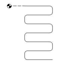
Select the drip area configuration: Snaking: Calculates the drip area as one continuous line with one start and end point
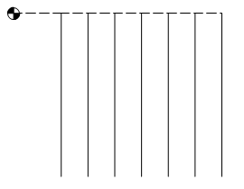
Branching: Calculates the drip area as several lines that branch out to fill the area; this configuration will not generate “Exceeds Max Line Length at Pressure” warnings. Because the drip area’s layout cannot be determined exactly, calculated values are approximate.
Custom: Allows the Input Pressure and Flow values to be manually entered, for situations when the expected pressure and flow values are already known by the designer; this configuration will not generate "Exceeds Max Line Length at Pressure" warnings |
|
Length (Drip line) |
For drip lines, provides the length of drip line required |
|
Row Spacing (Drip area) |
Sets the spacing between the rows of drip lines within the drip area. For the Custom drip area Configuration, this value is for reporting purposes only and is not used for calculations. |
|
Estimated Length (Drip area - Snaking) |
Displays the estimated length of drip line required for the area |
|
Override Estimated Length (total tubing) (Drip area - Snaking) |
Changes the estimated length of total drip tubing to a different value |
|
Length (Drip area - Snaking) |
Enter the override value for the length of tubing required |
|
Est. Avg. Line Length (Drip area - Branching) |
Displays the estimated average length of each branch of drip tubing in the configuration |
|
Use Default Trench Depth |
Uses the default trench depth specified in the irrigation settings; deselect to enter the trench depth manually |
|
Trench Depth |
Displays the default trench depth, for informational purposes; when Use Default Trench Depth is deselected, enter the trench depth |
|
Display in Drawing |
Select either Design Information or Calculated Information to affect the display of all calculated values and coverage zones in the drawing; see Concept: Design and calculation parameters for irrigation |
|
Design Information |
|
|
Input Pressure |
Specifies the optimal input pressure for the drip outlet to perform as designed. Enter this value manually for the Custom drip area Configuration. |
|
Flow |
Displays the drip outlet’s calculated flow rate based on the design Input Pressure. If you are modifying catalog data, this becomes editable. Enter this value manually for the Custom drip area Configuration. |
|
Calculated Information |
|
|
Input Pressure |
Displays the input pressure based on the entire system’s calculated parameters |
|
Flow |
Displays the flow rate based on the entire system’s calculated parameters |
|
Catalog Data |
|
|
Get From Catalog |
Opens the Catalog dialog box, for obtaining catalog data for the selected object (typically, this is for adding catalog data to a custom object that has none). See Concept: Using the irrigation catalog. |
|
Data |
Displays the catalog data |
|
Modify Catalog Data |
Makes the data fields editable; modify the data, which can then be saved as a custom entry in the catalog |
|
Save In Catalog |
Opens the Catalog Item Edit dialog box, where the custom data can be further edited and then added to the catalog |
|
Graphics |
|
|
Show Drip Lines (Drip area) |
Represents the drip area as a set of parallel lines; deselect the option to use the Fill Style from the Attributes palette instead |
|
Attach Tag/Label |
Automatically attaches a Tag/Label object to the object. The last selected tag/label for the object type is applied; click the tag/label to edit its properties (see Adding labels to irrigation objects). |
|
Show Pressure |
Places a pressure label on the drawing |
|
Show Flow |
Places a flow rate label on the drawing |
|
Vertex parameters |
Edits the vertices of the path object that the drip outlet is based upon; see Editing vertex-based objects |


