 Placing outlets
|
Tool |
Tool set |
|
Outlet
|
Irrigation |
The Outlet tool places an irrigation outlet with parameters from a selected manufacturer, or as a custom outlet with parameters that can be specified after placement.
There are several outlet types available for placement.
Rotors are large outlets which throw water over long distances as a single stream that rotates around the outlet.
Spray outlets spray water continuously over the set coverage area. They consist of two components: the body and the nozzle, in various configurations.
Emitters (drip nozzles) are inserted into drip tubing, and slowly leak water into the soil.
Because emitters do not have a throw radius, when placing them in any multiple-placement mode, the radius parameter and the radius preview indicate the spacing between emitters.
An outlet added to a pipe splits the existing pipe in two.
|
Mode |
Description |
|
Standard Insertion
|
Inserts an outlet according to the selected placement mode |
|
Pick Up
|
Sets the default outlet settings to match those of a selected existing outlet; see Transferring outlet attributes |
|
Convert
|
Places outlets on or within a valid object (pipe or polyline); see Transferring outlet attributes |
|
Outlet |
Opens the Resource Selector to select an outlet resource for placement; double-click a resource to activate it. Select from one of the manufacturer libraries, or select an outlet closest to the type you need from Custom.vwx and set its properties after placement. |
|
Single Outlet Placement
|
Places a single outlet as configured
|
|
Poly-Vertex Placement
|
Places a configured outlet at each clicked polyline vertex
|
|
Poly-Edge Space
|
Places outlets along the drawn polyline with the Tool Linear/Array Settings specified in the tool preferences
|
|
Rectangular Array
|
Fills the drawn polyline with outlets in a rectangular array with the Tool Linear/Array Settings specified in the tool preferences
|
|
Triangular Array
|
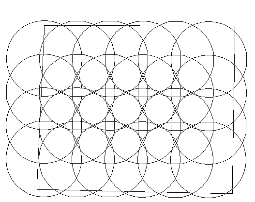
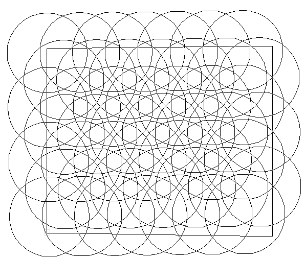
Fills the drawn polyline with outlets in a triangular array with the Tool Linear/Array Settings specified in the tool preferences
|
|
R (radius) |
Defines the default throw radius of the spray for rotors and spray outlets, or the spacing between emitters. If the outlet came from a manufacturer’s catalog, select one of the available throw Radius values, or select Manual or Manual Arc to specify the radius at placement. For certain outlets, select Manual Strip to place a strip outlet. For outlets only, browse through the radius values in the Tool bar list by pressing the shortcut key, and browse backwards through the list by pressing Shift + the shortcut key. For a custom outlet, the throw radius is determined at placement; select Manual Arc to place a circular outlet with the arc manually specified, or Manual Strip to place a strip outlet. |
|
Arc |
Defines the spray pattern coverage in radial degrees; does not apply to emitters. If the outlet came from a manufacturer’s catalog, select one of the available Arc spray pattern values, or select Manual to specify the spray pattern arc at placement. For a custom outlet, the spray pattern arc is determined at placement; if Manual Arc was selected for the Radius, Manual is preselected here and no other selection is necessary. For Manual Strip outlets, select the location of the outlet along the strip. |
|
Preferences
|
Sets the default preferences for the outlet placement and appearance |
To place outlets on the drawing:
Click the tool and then click Standard Insertion mode from the Tool bar.
Click Outlet on the Tool bar to select a resource from the Resource Selector. Select from one of the manufacturer libraries, or select an outlet closest to the type you need from Custom.vwx and set its properties after placement.
Click the placement mode from the Tool bar.
Click Preferences to open the Object Properties dialog box and specify the tool’s default parameters for placement and appearance. The Outlet tool uses these preferences until they are changed again, or until Pick Up mode is selected, which changes the settings to those of a selected existing outlet. Many of the parameters can be edited later from the Object Info palette.
Click to show/hide the parameters.Click to show/hide the parameters.
|
Parameter |
Description |
|
Tool Linear/Array Settings |
Specifies the outlet settings when placing outlets along a line or in an array |
|
Mode |
Select the placement mode, to control the spacing of multiple outlets. Overlap: Overlaps the throw radius of each outlet, or the distance between emitters, by the percentage specified in Value Fixed: Places outlets at the set distance specified in Value Best Fit (by distance): Places outlets at the start and end of the line or array, and then distributes the outlets evenly with spacing at or greater than the distance Value Best Fit (by overlap): Places outlets at the start and end of the line or array, and then distributes the outlets evenly with spacing at or greater than the minimum radius overlap Value percentage By Count: Distributes the specified number of outlets evenly along the line or within the array |
|
Value |
Specifies the overlap percentage, distance, or count |
|
Offset Along Spray Direction |
When placing non-360° arc outlets along the edge of a border or patio, offsets the outlets and the coverage in the direction of the spray |
|
Offset |
Sets the offset distance |
|
Object Defaults |
|
|
Outlet Name |
Names the object, which is useful for labels, irrigation schedules, and other worksheets |
|
Note |
Adds a note about the object, which is useful for labels, irrigation schedules, and other worksheets, and also for making notes when saving red symbol definitions |
|
Outlet Type |
Displays the type of outlet to be placed, based on the Outlet list selection in the Tool bar |
|
Graphics |
|
|
Symbol Name |
Displays the name of the symbol set and variation used to represent the outlets; <default symbol> indicates that the default outlet symbol set is used |
|
Replace Symbol |
Selects a different set of outlet symbols; specify the symbol from the list. Regardless of the specific symbol selected, the appropriate symbol from the set is automatically assigned according to the spray pattern arc. |
|
Symbol Offset |
Specifies the offset distance of the outlet symbol from the actual insertion point |
|
Symbol Scale |
Scales the symbol with respect to the layer scale by the specified scale factor; a factor of less than one decreases the size of the symbol, while a factor of more than one increases its size |
|
Symbol Rotation |
Indicates the default method to orient each outlet symbol at placement: No Rotation: Keeps the outlet symbol rotation in its default orientation Toward Coverage: Rotates the outlet symbol towards the center of the coverage area; does not apply to 360° radius Toward Coverage - Non Poly Only: Rotates the coverage arms of the symbol towards the center of the coverage area, without rotating the main symbol body
|
|
Show Coverage |
Displays an approximate planar representation of the throw radius and spray pattern arc |
|
Show Coverage 3D |
Displays an approximate 3D representation of the throw radius and spray pattern arc, based on trajectory and distance |
|
Show Pressure |
Places a pressure label on the drawing |
|
Show Flow |
Places a flow rate label on the drawing |
Click once to set the outlet location. If placing the outlet over an existing pipe, drip tubing, or irrigation pipe network, the connecting pipe is highlighted and the outlet is automatically connected to the network.
For arc outlets, move the cursor and click to set the throw radius. If the outlet was selected from a catalog, the cursor snaps automatically to the predefined radius values specified by the catalog; refer to the Data bar for the radius values. If a custom outlet is being placed or a custom radius defined, move the cursor to specify the radius at placement and click. For emitters, the drawn radius indicates the emitter spacing.
For strip outlets, click to set the start of the strip, and then move the cursor to set the width and height of the rectangular strip.
Click again to set the outlet spray pattern arc (if not set by the catalog value) and orientation, or for strip outlets, to finish drawing the strip.
A single outlet has been placed and oriented.

For multiple outlet placement, continue by drawing a line or a polyline, depending on the placement method selected. A dynamic preview of the outlets displays to help with placement. Double-click to place the outlets.
Adjust the position of any pressure and flow labels by dragging the control point. Adjust the radius, arc, and rotation of spray outlets with the coverage control points, when the spray coverage is visible. Catalog data requirements may constrain the allowable adjustments.

The parameters can be edited from the Object Info palette.
Click to show/hide the parameters.Click to show/hide the parameters.
|
Parameter |
Description |
|
Save Outlet |
Saves the selected outlet as a red symbol definition in the active file; this would typically be done for a custom outlet, or an outlet with modified catalog data |
|
Outlet Name |
Names the object, which is useful for labels, irrigation schedules, and other worksheets |
|
Note |
Adds a note about the object, which is useful for labels, irrigation schedules, and other worksheets, and also for making notes when saving red symbol definitions |
|
Outlet Type |
Indicates the type of outlet that was placed |
|
Display in Drawing |
Select either Design Information or Calculated Information to affect the display of all calculated values and coverage zones in the drawing; see Concept: Design and calculation parameters for irrigation |
|
Design Information |
|
|
Input Pressure |
Specifies the optimal input pressure for the outlet to perform as designed |
|
Flow/Radius |
Displays the outlet's flow rate and, if applicable, throw radius based on the design Input Pressure. If you are modifying catalog data, this becomes editable. |
|
Radius Reduction (rotor only) |
Reduces the throw radius by the set percentage, as permitted by the catalog data |
|
Calculated Information |
|
|
Input Pressure/Flow/Radius |
Displays the calculated input pressure, flow rate, and throw radius based on the entire system’s calculated parameters |
|
Radius Reduction (rotor only) |
Fine tunes the throw radius by the set percentage, as permitted by the catalog data |
|
Catalog Data |
Spray outlets have separate catalog sections for the nozzle and the body components |
|
Get From Catalog |
Opens the Catalog dialog box, for obtaining catalog data for the selected object (typically, this is for adding catalog data to a custom object that has none). See Concept: Using the irrigation catalog. |
|
Data |
Displays the catalog data. For rotor and spray outlets, the Pressure Regulation parameter determines whether the outlet's performance will be limited by the recommended pressure. When selected (displaying as True), the recommended pressure serves as an upper limit on the pressure, and therefore, it limits the outlet’s performance. |
|
Modify Catalog Data |
Makes the data fields editable; modify the data, which can then be saved as a custom entry in the catalog |
|
Save In Catalog |
Opens the Catalog Item Edit dialog box, where the custom data can be further edited and then added to the catalog |
|
Graphics |
|
|
Symbol Name |
Displays the current name of the symbol set and variation used to represent the outlet; <default symbol> indicates that the default outlet symbol set is used |
|
Replace Symbol |
Selects a different set of outlet symbols; specify the symbol from the list. Regardless of the specific symbol selected, the appropriate symbol from the set is automatically assigned according to the spray pattern arc. |
|
Symbol Offset |
Specifies the offset distance of the outlet symbol from the actual insertion point |
|
Symbol Scale |
Scales the symbol with respect to the layer scale by the specified scale factor; a factor of less than one decreases the size of the symbol, while a factor of more than one increases its size |
|
Symbol Rotation |
Indicates the default method to orient the outlet symbol: No Rotation: Keeps the outlet symbol rotation in its default orientation Toward Coverage: Rotates the outlet symbol towards the center of the coverage area; does not apply to 360° radius Toward Coverage - Non Poly Only: Rotates the coverage arms of the symbol towards the center of the coverage area, without rotating the main symbol body
|
|
Attach Tag/Label |
Automatically attaches a Tag/Label object to the object. The last selected tag/label for the object type is applied; click the tag/label to edit its properties (see Adding labels to irrigation objects). |
|
Show Coverage |
Displays an approximate planar representation of the throw radius and spray pattern arc |
|
Show Coverage 3D |
Displays an approximate 3D representation of the throw radius and spray pattern arc, based on trajectory and distance |
|
Show Pressure |
Places a pressure label on the drawing |
|
Show Flow |
Places a flow rate label on the drawing |


