Quick Start: Let's add some dimensions
Difficulty level: Beginner
You can add dimensions directly to drawing objects on a design layer, or add them as viewport annotations. The automatic Dimension class makes it easy to customize the color and text of the dimensions.
In this project, you'll do the following:
Set the document units for dimensions
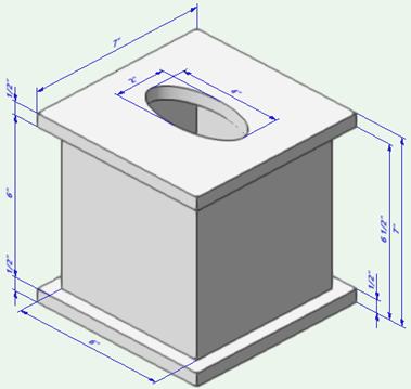
Model a simple tissue box and add dimensions to it
Edit the Dimension class
Create a text style for dimensions
Add dimensions as annotations in a viewport
The location of commands and tools varies, depending on the workspace. You can learn to use the Quick Search feature to quickly find commands or tools; see Quick Search. You can also look at the Commands and tools PDF here in the Vectorworks help system.
Set the document units for dimensions
Select the New command to open a new, blank file. The drawing opens in Top/Plan (2D) view.
Since you're going to draw a small box, reduce the default layer scale. Right-click and select Active Layer Scale to open the Layer Scale dialog box. Select the 1:2 setting.
Next, select File > Document Settings > Units. The Dimensions pane controls how units display in dimensions. For this tutorial, change the settings as follows:
Units = Inches
Rounding style = Fractional
Fraction precision = 1/8
Draw the box bottom
You need a 3D object that you can add dimensions to. Let's create a tissue box.
On the View bar, select Right Isometric from the Current View/Standard Views list, or just press 3 on your numeric keypad or use the Onscreen View Control cube to switch to a 3D view.
Click the Rectangle tool  , and from the Tool bar, click Corner to Corner mode
  .
.
Click and drag to draw a 7" square. Click again to create the square.
Hover the cursor over the square. The red highlight indicates that Push/Pull mode  is active; click and move the cursor upward to create a 1/2" extrude.
Draw the box sides
From the Tool bar, click Center to Corner mode  of the Rectangle tool.
Hover the cursor over the box bottom. The purple highlight indicates the automatic working plane, which means that the next object you draw will be placed on that surface. Click in the center of the extrude surface and drag toward a corner. Click to create a 6" square.
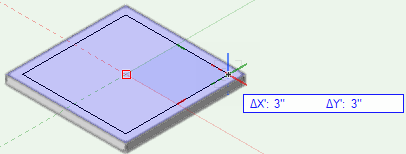
Hover over the square to access Push/Pull mode again. Drag upward and click to create an extrude with a 6" height. In the next steps, you're going to "push" the inside of this extrude downward, leaving 1/2" box sides.
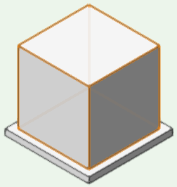
From the Tool bar, click the Push/Pull Combine mode  of the Rectangle tool.
Click in the center of the box extrude surface and drag toward a corner; click to create a 5" square.
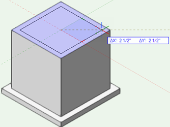
Hover over the square to access Push/Pull mode. Drag downward past the bottom of the extrude (-6 1/2") and click to complete the push operation.
Draw the box top
Click the Selection tool  . While pressing the Ctrl key, click the bottom left corner of the box bottom and drag it straight upward to create a duplicate extrude 6 1/2" above the box bottom.
Click the Oval tool  , and then click the Center mode
  from the Tool bar.
Hover the cursor over the box top to activate the automatic working plane. Click in the center of the extrude surface and move the cursor toward one edge. Click to set the minor radius of the oval at 1". Then move the cursor toward an adjacent edge; click to set the major radius at 2" and create the oval.
Hover over the oval and drag downward to a distance of -1" to cut a hole in the top. Don't worry, we're not going to model any tissues. It's time to dimension!
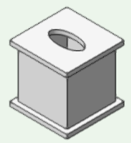
Add dimensions
Click the Unconstrained Linear Dimension tool  , which lets you create dimensions at any angle.
From the Tool bar, select one of the preset dimension standards (Standard) and the document units (Units).
You can make a custom dimension standard and custom dimension units to meet specific requirements.
Use each of the tool modes to dimension different parts of the box. Click two points to dimension, and drag away from the object to preview both the length of the witness lines and the plane the dimension will be placed on. Click to set the dimension location.
If the mode can show multiple dimensions, click all the points you want to include, and double-click the last point to complete the dimension.
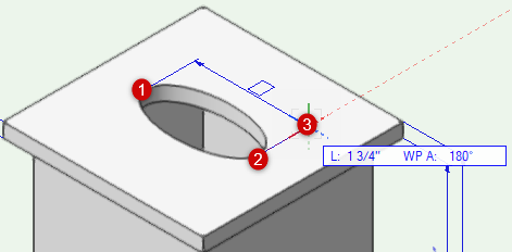
There are three modes available:
Unconstrained Linear  : Dimension with a single measurement
Unconstrained Chain  : Continuous chain of dimensions
Unconstrained Baseline  : Set of dimensions measured from the same baseline point
Add a set of unconstrained baseline dimensions
If you need to move the text portion of a dimension for readability, use the Selection tool to select the text box and drag it to the new location. You can move the dimension line in the same way.
Edit the Dimension class
You might want the dimensions to have a custom font, or a specific color. All dimensions are automatically placed in the Dimension class, so you can edit the class to easily change all dimensions at once.
Note that the class settings don't control all parts of the dimension.
Color, line thickness, and text style are controlled by the Dimension class
Font, size, and style are controlled by the text style (which is part of the class settings)
Line markers are controlled by the dimension standard (which is on the Tool bar for all dimension tools)
To edit the Dimension class:
Select Tools > Organization (or press Ctrl+Shift+O) to open the Organization dialog box.
Select the Dimension class, and click Edit to open the Edit Class(es) dialog box.
From the Graphic Attributes pane, click the Use at Creation option, and change the pen Color and Thickness. (Remember, the Markers setting here won't have any effect.) If you don't want a background behind the dimension text, you can also change the fill Style to None.
Next, create a new text style for your dimensions. In the Text Style section of the dialog box, check the option Use at Creation. From the Text Style list, select New to open the Create Text Style dialog box.
Enter a Style Name, and select whatever Font, Size, and Font Style you like. (Remember, the Color settings here won't have any effect.) If prompted, confirm that you want to change the existing dimensions.
When you save the class settings, the dimensions in the drawing are updated.
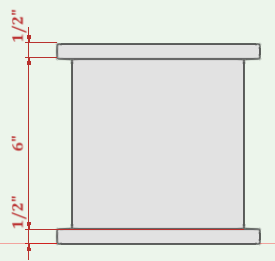
Add dimensions to a viewport
A sheet layer viewport provides a view of a model, such as a rendered elevation, or a cross section detail. The viewport contents can be rendered and annotated as needed. If the drawing changes, you can easily update the viewport to reflect the changes.
Up to this point, you were adding dimensions to a design layer. Now you'll add dimensions to the annotation space of a viewport. For a 3D object, the face you're adding a dimension to must be aligned with the screen plane to get an accurate measurement.
Select the tissue box parts, and then switch to Top view.
Press the Ctrl key as you drag to create a duplicate box several inches away from the original box. You're going to create a cropped viewport from this box so that you can add dimensions to it.
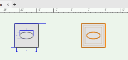
Use the Rectangle tool to draw a rectangle around the duplicate box. With the rectangle still selected, select View > Create Viewport. When prompted, confirm that you want to use the rectangle as the viewport's crop.
In the Create Viewport dialog box, click Create on Layer and select New Sheet Layer. On the New Sheet Layer dialog box, accept the default values and click OK to create the sheet layer.
Back on the Create Viewport dialog box, enter a Drawing Title and click OK to create the viewport.
The new sheet layer displays, with the viewport selected. Right-click the viewport, and select Edit Annotations. The drawing area has an orange border to indicate you're in editing mode.
Since the viewport is in Top view, click the Constrained Linear Dimension tool  , which constrains the dimension lines to the X or Y axis of the plane where the dimension is created. Add some horizontal and vertical dimensions to the box. Click Exit Viewport Annotation to exit editing mode.
You can place multiple viewports on the same sheet layer to show different views of the same objects.
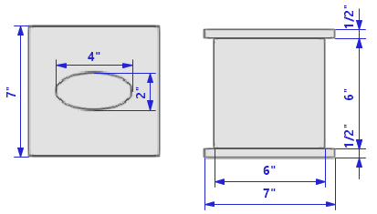
Two viewports showing the box dimensions in Top view (left) and Front view (right)
