The Onscreen View Control
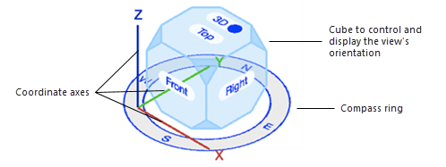
The Onscreen View Control displays in the lower left corner of the drawing area for design layers. It lets you quickly change among standard views, or drag to execute a flyover and set custom views. Depending on the settings, the Onscreen View Control also provides visual cues to the drawing orientation, including coordinate axes, a compass ring, and indicators for a rotated Top/Plan view and/or when the view is set relative to the working plane. Zooming with the mouse wheel when the cursor is located over the cube uses the center of the view pane as the zoom origin, rather than the cursor position.
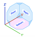
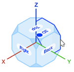
When View is Relative to Working Plane is enabled, the Onscreen View Control orients itself so the bottom face of the cube is parallel to the working plane, and the bottom face displays in a color to reflect the working plane alignment.
When multiple view panes are enabled, the Onscreen View Control displays only in the active pane.
Standard views
Use the Onscreen View Control to change among standard views from within the drawing area (see Using standard views).
To change to a standard view, do any of the following:
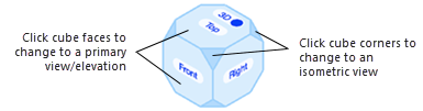
Click any cube face or angled corner to change to the associated standard view.
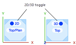
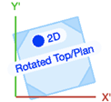
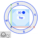
To change to Top/Plan view, click the 2D/3D toggle on the Top cube face from any view where it is visible; you may need to change the current 3D view to make the Top face visible.
If there is a rotated Top/Plan view available, the 2D toggle activates that rotated view (see Rotating the plan).
To change to a primary standard view from an occluded side of the cube, hold the cursor over the nearest edge of the cube face until the occluded side's edges are highlighted, and then click. Isometric views set by occluded corners cannot be directly selected; change first to a view that makes the necessary cube corner accessible.
To change to the view directly opposite the current standard view, click on the current view face or corner.
The Current View list on the View bar shows the name of the current view.
Flyover and custom views
You can also use the Onscreen View Control to manually fly over the model, and to set a custom view. The Onscreen View Control's flyover function uses the Flyover tool's View Center mode behavior, the shortcut keys to control how the flyover responds to mouse movements, and the rotation sensitivity set in the Flyover Preferences dialog box; see Flyover.
To fly over the model using the Onscreen View Control:
Click the Onscreen View Control cube, and drag to change the view's orientation; the flyover cursor  displays. Readjust the cursor location over the cube as needed, and/or click a cube face or corner to change to an appropriate standard view from which to begin the flyover.
Onscreen View Control appearance
You can set which parts of the Onscreen View Control display, and change its size and the colors of some parts.
To control the visibility of the Onscreen View Control parts:
Move the cursor toward the lower left corner of the drawing area (whether the Onscreen View Control is currently visible or not) until the menu button displays; click the button.
The Onscreen View Control Settings popover opens.
These are application settings, not document settings.
Click to show/hide the parameters.Click to show/hide the parameters.
|
Parameter |
Description |
|
Show Onscreen View Control |
Displays all or part of the Onscreen View Control as indicated by the selections below |
|
Show axes |
Displays the X/Y/Z or X'/Y'/Z' axes, depending whether the axes are relative to the layer plane or working plane |
|
Show compass ring |
Displays the compass ring, if Location and orientation of the internal origin is manually enabled on the Document Georeferencing dialog box; see Specifying document georeferencing. The compass ring is for informational purposes only, and can't be used to change settings. Location and orientation of the internal origin is enabled by default when a Design Suite product is licensed, but since many designers don't use this feature, the compass ring is available for display only when the Document Georeferencing dialog box is opened, and OK is clicked with the parameter enabled. |
|
Show cube |
Displays the cube |
To change the size and the colors of some Onscreen View Control parts:
Set the desired size and colors in Vectorworks preferences; see Interactive appearance settings.