Inserting stake objects
|
Tool |
Tool set |
|
Stake
|
Design Suite, Architect, Landmark: Site Planning |

Stake objects represent a 3D point in space, with text to display the elevation, coordinate points, or other information. The information can be displayed using either the built-in tag or a data tag. A stake object can be used as a site modifier, for spot heights of 3D objects, and to display user origin coordinates. If the file and design layer are georeferenced, a stake object can also be used as a geographic marker.
In addition to using the Stake tool, multiple stakes can also be inserted in a grid pattern as described in Adding source data by grid method entry.
|
Mode |
Description |
|
Standard Insertion
|
Inserts a single stake object |
|
Vertex
|
Inserts a stake at each vertex of the drawn polygon shape |
|
Preferences
|
Sets the default preferences for the stake object, including automatic numbering settings |
|
Elevation |
Sets the default elevation value for stake objects |


To insert a stake object:
Click the tool and mode. If desired, set the default Elevation value in the Tool bar.
To automatically label stakes with an incrementing number as they are placed, click Preferences. Specify an ID Reference Label and set the automatic ID labeling as described below.
Click in the drawing or on the site model (either proposed, or more rarely, existing) to place the stake object. In Vertex mode, draw a temporary polygon to place a series of stake objects at each click point and double-click to end the series.
The first time you use the tool in a file, a properties dialog box opens. Set the default parameters. The parameters can be edited later from the Object Info palette.
The stake object is added to the drawing, at the elevation in the Tool bar if specified.
The stake label displays the selected information from the model (such as coordinates or elevation), or the specified information (such as ID or description).
If the stake objects are site modifiers, update the site model to apply the changes (select the site model and click Update from the Object Info palette).
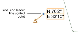
If using the data tag, the data tag's setup will determine the label position and shoulder setting. If using the built-in tag, move the control point to adjust the label and leader line position. If there are several stake objects, use the Align/Distribute Leader Lines command to improve readability (see Aligning and distributing leader lines).
The stake parameters can be edited from the Object Info palette.
Click to show/hide the parameters.Click to show/hide the parameters.
|
Parameter |
Description |
|
Z-value |
Specifies the stake elevation. To create road stakes with the Vectorworks Landmark product, set the elevation of the first stake along the polyline; the elevation of the remaining stakes is automatically calculated (as described in Setting stake elevations). |
|
Rotation |
Rotates the stake object indicator and the label (if applicable) around the stake object indicator’s center |
|
Mode |
|
|
Include as Site Model Data |
Uses the stake as site model data if it is located in the source data layer (select when using stakes to create a site model) |
|
Set Elevation to Site Model Grade |
Sets the stake elevation to the existing or proposed site model grade. This also applies to stakes placed on draped hardscapes and landscape areas. |
|
Set Elevation to Site Model Cut Surface |
Sets the stake elevation to the proposed site model surface, at the bottom of any excavations for hardscape and landscape areas |
|
Set Elevation to Object Spot |
Sets the stake elevation to any 3D object where the stake has been placed. If paired with the label reference Object Spot Height Above Grade, shows the height over the site model grade. |
|
Use as 2D/3D Graphic Only |
Uses the stake for annotations that don't interact with the objects it's placed over |
|
Site Modifier Object |
Treats the stake object as a site modifier, which has an effect on the site model |
|
Reset Stake |
Resets selected stake(s) in Set Elevation to Object Spot mode |
|
Reset All Stakes |
Resets all stakes in Set Elevation to Object Spot mode |
|
Site Model |
When the stake object is used as a site modifier, specifies whether it affects the existing or proposed site model |
|
Use Annotation |
Selects the built-in tag or data tag. The Stake Text data tag can display the information selected in the Label Reference, but with more flexibility in its appearance than the built-in tag. The data tags can combine data from the stake with other criteria specified in the data tag settings. |
|
Data Tag Style |
Click the data tag selector to select a resource from the Resource Selector; double-click a resource to activate it |
|
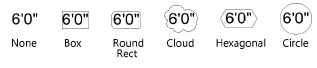
Bubble Style (Built-in Tag) |
For built-in tag annotations, selects the graphic style of the bubble drawn around the stake’s value
|
|
RR Corner Radius (Built-in Tag) |
For Round Rect bubble styles, sets the corner radius |
|
Text Margin (Built-in Tag) |
Sets the distance between the bubble and the text |
|
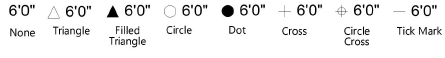
Top/Plan |
Selects the graphic style of the stake object indicator
|
|
3D Display |
Sets the appearance of the stake object in 3D views. None: no 3D display is created; the stake object displays like a 2D planar object. Locus: a 3D locus is displayed. Extrude: a rectangular extrude extends upward from the stake elevation; specify the width and height of the extrude. |
|
Mark Offset X |
Offsets the stake object indicator from the insertion point along the X axis |
|
Mark Offset Y |
Offsets the stake object indicator from the insertion point along the Y axis |
|
Mark Rotation |
Rotates the stake object indicator around its center |
|
Label Reference
|
Selects the type of information to display in the stake's label; the available label fields depend on the label reference selected. Specific information is provided in the rows below. ID: Displays an ID Number that you specify, along with an optional prefix/suffix. Stakes can be automatically labeled with an incrementing ID number when this is set in the Stake Tool Preferences before placing stakes. Elevation: Displays the stake elevation (layer elevation Z height); select the Elevation Units (or use the default Document Units) and the Elevation Prec (precision). Description: Displays a Decription that you specify. Stationing Data: If the stake is used as a station point, displays the station point data (Landmark required). Coordinate Point: Displays the Northern/Easting, Easting/Northing, XY, or YX coordinates of the stake. Select a Coordinate Unit such as feet and meters or the default, Document Units. Latitude or Longitude: Displays the latitude/longitude or longitude/latitude if the design layer is georeferenced; the Decimal Degrees unit is automatically selected. Object Spot Height Above Grade: Displays the elevation of the stake above the site model surface; select the Elevation Units (or use the default Document Units) and the Elevation Prec (precision). No Label: Does not display a label with the stake. |
|
Label Position (Built-in Tag) |
For built-in tag annotations, specifies the alignment of the label, and which side to place the leader line (when displayed): Auto: Automatically determines whether to place the text on the left or right, depending on the position of the label related to the stake's location Right: Places the text to the right of the label control point and left-justifies the text Left: Places the text to the left of the label control point and right-justifies the text Center: Centers the text on the label control point |
|
Description (Description Label Reference) |
Enter description text |
|
ID Prefix/Suffix (ID Label Reference) |
Enter a prefix to display before the ID number or suffix to display after the number |
|
Auto ID Numbering (ID Label Reference; only available when placing new stake objects) |
Automatically increments the ID Number parameter as stakes are placed |
|
(Initial) ID Number (ID Label Reference) |
Specifies the ID number. When Auto ID Numbering is selected, the ID Number field changes to Initial ID Number, and ID numbers are automatically incremented beginning with the initial number specified. When Auto ID Numbering is not selected, specify or edit an ID Number for the selected stake object. |
|
Station Point Data (Stationing Data Label Reference) |
For Stationing Data labels, indicates the station point data for the selected stake object. This applies when the stake is placed along a polyline, and station points have been created for the stake (such as a road). Landmark required; see Creating a roadway with the Vectorworks Landmark commands. |
|
Coordinate Point (Coordinate Point Label Reference) |
Coordinate point type labels can show the stake's distance from a point of origin (user origin). Specify Document Units, Feet, or Meters as the Coordinate Units and specify the Coordinate Prec (precision). The Coordinate Point (NE - Northing-Easting) and Coordinate Point (EN - Easting-Northing) options display the distance prefixed with the direction (N, W, S, E). The Coordinate Point (XY) option displays user origin coordinates (X, Y). If the stake object or user origin moves, the coordinates automatically update to reflect the change. |
|
Show Elevation (Coordinate Point Label Reference) |
Displays the elevation along with the other coordinates |
|
Elevation Units (Coordinate Point and Elevation Label Reference) |
Specifies the units to use for the elevation. Select Document Units to use the same units as the document, or select an imperial or metric unit. |
|
Elevation Prec (Coordinate Point and Elevation Label Reference) |
For elevation and coordinate point type labels where the specified elevation units are not set to Document Units, specifies the precision with which the measurements are labeled |
|
Show unit mark (Coordinate Point and Elevation Label Reference) |
For elevation and coordinate point type labels, displays the unit mark along with the unit value. For coordinate point type labels, if Document Units are set for Coordinate Units, the unit mark visibility is determined by the document setting. |
|
Display Leader Line (Built-in Tag) |
Adds a leader line from the label to the stake object (adjust the leader line position by moving the leader line control point) |
|
Scale Factor |
Determines the size of the stake object indicator |
|
Set Geolocation (Coordinate Point and Longitude or Latitude Label Reference) |
Opens the Set Geographical Location dialog box, to move the stake to the specified coordinates related to georeferencing. The dialog box displays the coordinates of the current stake location; changing these doesn't affect the geolocation of the project—it moves the stake to the specified coordinates. See Adding a GIS Stake. |