 Creating
Custom Circuit SymbolsCreating
Custom Circuit Symbols
Creating
Custom Circuit SymbolsCreating
Custom Circuit SymbolsElectrical and communication circuit symbols can be created specifically to fulfill a custom requirement.
To create a circuit symbol:
Draw the object to represent the circuitable symbol.
Convert the object into a symbol by selecting Modify > Create Symbol. Provide a name for the circuitable item. See Creating New Resources.
If the file does not contain a circuiting record, create the record according to the following format.
Field |
Type |
Contents |
Name |
Text |
None |
Circuit # |
Integer |
0 |
Wire Size |
Text |
0 |
Trip |
Integer |
0 |
Conduit Size |
Text |
1/2 |
V.A./Watts |
Integer |
0 |
Remarks |
Text |
Panel |
Phase/Pole |
Integer |
2 |
Voltage |
Text |
0 |
Circuit Type |
Integer |
1 for electrical device, 2 for communication device |
UID |
Text |
0 |
ID |
Text |
0 |
Select the symbol from the Resource Browser, and then click Edit from the Resources menu.
The Edit Symbol dialog box opens.
Click 2D Component, and then click Edit.
In the Edit Symbol window, deselect all symbol components.
Attach the circuiting record to the symbol by selecting it from the Data tab in the Object Info palette. Fill out the circuiting information by selecting a record field and entering its record information; this information is displayed and edited by the circuiting tools.
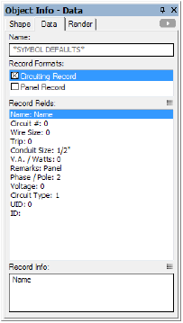
Click to show/hide the parameters.
If the symbol requires more than one circuit, create and attach a second identical record named Circuiting Record-1.
Click the Exit Symbol button located at the top right of the drawing window.
~~~~~~~~~~~~~~~~~~~~~~~~~
![]()