 Inserting
a Custom LightInserting
a Custom Light
Inserting
a Custom LightInserting
a Custom LightA custom light source’s emission distribution can be defined by a standard intensity distribution profile for accurate physical lighting.

To create a custom light:
Select the Light tool from the Visualization tool set, and then select Custom Light from the Tool bar.
Specify the custom light parameters by selecting Preferences from the Tool bar.
The Custom Light Data dialog box opens. Click Load Distribution and specify the location of the custom light distribution file, and then specify any additional custom light parameters.
Click to show/hide the parameters.
Click OK.
The Light Preferences - Custom Light dialog box opens. Specify additional custom light parameters. Emitter parameters are specified by the distribution file, and cannot be changed.
Click to show/hide the parameters.
Click OK to return to the drawing.
Click in the drawing to insert the custom light.
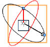
The custom light object is represented by a pair of perpendicular arrow-head vectors and two perpendicular circles. The black vector points to the target location; its axis line (the light axis) connects the light source location to the target. The red vector starts at the light source location, pointing to a reference point on the “equator” of the polar intensity distribution. Also known as the “zero angle line,” it represents the origin for measuring the intensity on the light curve.
The two vectors form the black circle, and the red circle is perpendicular to it. The black circle represents the original plane where the light curves are located. The red circle constrains the movement of the zero angle line.
After a custom light has been placed, the light parameters can be edited in the Object Info palette.
~~~~~~~~~~~~~~~~~~~~~~~~~
![]()