 Lighting Instrument Specifications
Lighting Instrument SpecificationsSpecial rules apply when creating a symbol to be converted to a lighting instrument.
Symbols should be hybrid (2D/3D) so that they display properly in both 2D and 3D views. At a minimum, the symbol must contain a 2D component, which must be a screen plane representation and not a 2D planar object.
Create the 2D view of the symbol using as few polygons and lines as possible. If possible, use a single polyline rather than individual line segments. All instruments should be drawn with the front of the instrument (the end which emits light) oriented towards the top of the drawing. The symbol below was created from these few constituent parts:
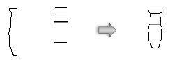
The line weight of the symbol is also a consideration; the instruments need to stand out when printed. The outer perimeter of the symbol should have a line weight of at least 1/2 point (7 mils). Interior details should use a lighter line weight.
The 2D representation should have a solid fill so that it obscures information under the symbol. The size of the instrument should be accurate based on the real instrument it represents. While drawing the instrument, keep the level of detail as minimal as possible. The goal is to be able to distinguish instruments from one another, not to create a detailed plan view of each instrument.
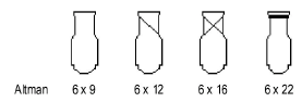
For instruments with multiple configurations, it is acceptable to use simple graphical differences to distinguish among the models. For example, use the following variations to separate the different versions of a symbol:
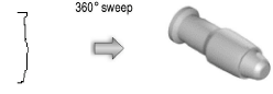
The 3D portion of the instrument should be drawn as if it is hung straight down (along the Z-axis) with the yoke oriented along the Y-axis. The top of the instrument should be oriented towards the top of the drawing. An easy way to generate a reasonable 3D instrument body is to sweep the 2D portion of the symbol. The segment angle of the sweep should be between 20 and 40°. See Sweeping Objects for more information.
Keep the 3D symbol simple. It should be solid. The model should be accurately sized, but without minute details like handles, grommets, fins, louvers, cords, and knobs. These items can add significantly to the rendering time required, and are not necessary to distinguish among instruments.
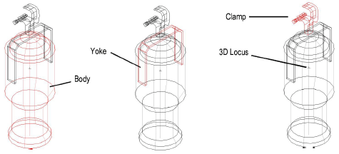
The 3D model should consist of three parts: the body, a yoke, and a clamp or base. Any subparts should be made into a single object or group for each of these pieces. The body represents the part of the instrument where light is emitted; the yoke connects the body to the base, and the base consists of either a base motor unit for moving lights or a clamp or other hanging device for other lights. The clamp can be imported from the symbol library provided with the Spotlight program. Place a 3D locus within the body of the instrument.
All the parts should be aligned as shown; the yoke rotates about the Z-axis, and the body rotates at the height of the locus point.
Align the 2D and 3D views so that the hanging points of both versions line up.
The insertion point of the 2D/3D hybrid symbol in Top/Plan view should represent the hanging location of the instrument. The 3D insertion point should be the hanging point (center of the clamp or base).
Create the symbol as described in Creating Symbol Definitions.
Attach the Parts record to each of the three pieces of the 3D instrument model: body, yoke, and base or clamp.
To attach the Parts record:
From the Resource Manager, locate a Parts record from one of the instrument library files included with the Vectorworks Spotlight program, and drag it to the active file. Alternatively, right-click on the record, and select Import from the context menu.
Select the new symbol, and select Modify > Edit Symbol.
In the Edit Symbol window, select the body, yoke, or base/clamp.
Click the Data tab in the Object Info palette. Click Attach Record to open the Resource Selector, and double-click the Parts record to attach it.
Select the Parts record, and select the appropriate body part (base, yoke, or body) from the record fields.
Repeat steps 3 through 5 for each of the three parts of the instrument model.
Click Exit Symbol at the upper right corner of the window to return to the drawing.
Attach the Light Info record to the lighting instrument symbol, with field names that match the names of the fields in the instrument object. This record format is required. Not all the fields are required, but the desired fields for the instrument object to read should be included. Filling the instrument type field with the manufacturer’s name and model name for the particular instrument is recommended.
The Light Info M record provides metric measurements of the weight and frame size of the instrument object. This record format is additionally needed for instruments that could be used in both imperial and metric drawings.
To attach the light info record:
From the Resource Manager, locate the Light Info Record and Light Info Record M from one of the instrument library files included with the Spotlight program, and drag them to the active file. Alternatively, right-click on the records, and select Import from the context menu.
Select the new symbol, and select Modify > Edit Symbol.
In the Edit Symbol window, click an empty location so that nothing is selected.
Click the Data tab in the Object Info palette. Click Attach Record to open the Resource Selector, and double-click the Light Info Record to attach it to the symbol. Select the record format from the list, and enter its record information.
The Candlepower, Beam Angle, and Field Angle parameters affect the photometric grid and photometer object calculations. The Beam Angle and Field Angle parameters affect the Draw Beam feature.
Normally, do not include text labels with the instrument, as these are handled by the instrument object. An exception can be made to distinguish different models or lamps of an instrument. For example, create three versions of a single PAR64 symbol by adding MFL, WFL, and NSP text blocks.
Symbols should be named with the model name of the lighting instrument.
Repeat step 4 to attach and edit the Light Info Record M.
Turn the lighting instrument’s light on in the Visualization palette to include a spot light as part of the lighting instrument. While editing the symbol, the spot light can be added, and accurate lighting information specified with the parameters in Use Emitter. See Adding Light Sources for information on adding a spot light and setting accurate lighting parameters.
Click Exit Symbol at the upper right corner of the window to return to the drawing.
As an alternative to the process of manually editing the symbol definition to attach the Light Info (and/or Light Info M) record, use the Lighting Symbol Maintenance command as described in Lighting Symbol Maintenance . Add the symbol by clicking New, and the Light Info record is automatically attached to it. Once in the maintenance list, the record data can be easily edited.
~~~~~~~~~~~~~~~~~~~~~~~~~