The Object Info Palette: Shape Tab
Use the Shape tab of the Object Info palette to view and edit object properties, as well as the shape of the object. Class and layer information displays for all objects. For most objects, Rotation displays, indicating the object’s orientation. Other object parameters, such as style, size, and graphic options, can be simple or very extensive depending on the object.
To view and edit shape information:
-
Click the Shape tab from the Object Info palette.
-
Select one or more objects.
-
If you selected multiple objects, select either Multiple Edit or Individual Edit mode, as described in Editing Multiple Objects.
-
Change the desired information, using the keys as follows:
Key
|
Function
|
|
Enter
|
Save the entry and return the focus to the drawing area
|
|
Tab
|
Save the entry and move the focus to the next editable field
|
|
Shift+Enter
|
Save the entry and keep the focus in the same field, so that you can enter a different value if necessary
|
Assigning Objects to Classes and Layers
Select a class/layer from the list of classes/layers present in the drawing, or create a new class/layer.
When you create a new class or layer from the Object Info palette, any selected objects are assigned to the new class/layer, but the active class/layer does not change to the newly created class/layer.
Classes can be displayed in hierarchical order (up to four levels). To enable or disable hierarchical display, see Vectorworks Preferences: Session Tab.
Alternatively, assign objects to classes and layers from the Navigation palette (Vectorworks Design Series required).
-
Select one or more objects to assign to a class or layer.
-
Select the Classes tab or Design Layers tab from the Navigation palette.
-
Right-click (Windows) or Ctrl-click (Mac) on the class/layer to assign the object to and select Assign to Selection from the context menu.
Object Coordinates and Bounding Box Indicator
The Shape tab can display a selected object’s plane, coordinate, and bounding box information. The information displayed depends on the type of object, the active plane, and whether it is in a rotated plan view (Vectorworks Design Series required) or positioned relative to a working plane.
For 2D objects, the plane to which the object belongs is indicated by the Plane list, and can be changed by selecting another plane from the list. For example, a screen plane object can be turned into a layer plane object by selecting Layer. When a working plane is active, the object can be moved to it. (If a combination of 2D and 3D objects are selected, the Plane list selection applies only to the 2D objects.)
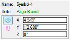
Symbols display the symbol’s name and units (whether world- or page-based). Symbols and solids can be scaled from the Object Info palette (see Scaling Symbols from the Object Info Palette and Scaling Solids Asymmetrically.)
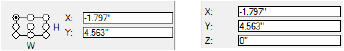
The Box Position indicator displays for certain 2D objects such as lines, walls, rectangles, and ovals. It represents the bounding box of the object, indicates which side is the width and height for objects with width and height, and uses a handle to indicate the fixed point about which the object can be resized. The handle is also the location from which the object coordinates are determined. When an object is rotated, the Box Position indicator rotates also, indicating the approximate position of the object and, if applicable, the width and height sides. For rectangles, rounded rectangles, and ovals, when the Rotation angle is less than ±45° from 90° or 270°, the software automatically swaps the height and width markers for the Box Position indicator and the values in the Height and Width fields.
Different object coordinates display for an object depending on its plane, position, and plan rotation.
When a Vectorworks Design Series product is installed, the coordinates menu preference also affects the display of coordinates in rotated plan view (see Rotating the Plan).
View
|
Coordinate Display
|
|
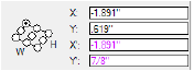
Top/Plan
|
Coordinates are relative to the screen plane (X and Y); coordinates for 2D/3D symbols also include the Z coordinate for a streamlined workflow between views
|
|
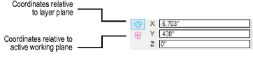
3D view with working plane active
|
Coordinates are relative to the layer plane (X and Y) and to the active working plane (X’, Y’). The working plane coordinates display in the same color set for the working plane itself in the interactive preferences.
|
|
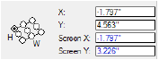
Rotated plan
(Design Series required)
|
Coordinates are relative to the layer plane (X and Y) and to the rotated plan (Screen X and Screen Y). The rotated plan coordinates display in blue, as do the rulers.
|
Some 3D objects, such as 3D polygons, NURBS curves, meshes, 3D symbols, spheres, cones, hemispheres, and 3D loci, can display coordinates relative to the layer plane (X, Y, Z)—also called the user coordinate system—or the active working plane (X’, Y’, Z’), when a working plane is selected. Click the planes button to change the relative coordinate display.
Some symbol instances are page-based at placement or upon import. These do not display a Box Position indicator in the Object Info palette. (The object can only be resized symmetrically.) The coordinates are relative to the screen plane (X and Y), and 2D/3D symbols also show the Z coordinate for a streamlined workflow between views.
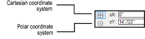
Some objects, such as lines and walls, can display and edit selected object information in either Cartesian or polar mode.
Coordinate System
|
Description
|
|
Cartesian
|
Cartesian coordinates are the same as those used in the drawing area; values are based on positive and negative X and Y axes
|
|
Polar
|
In polar mode, values are relative to the user origin. Angles are represented as positive or negative values from 0 to 180. Values from 180 to 359 are automatically converted to negative. 0 is at the 3 o’clock position.
|
Editing Vertex-Based Objects
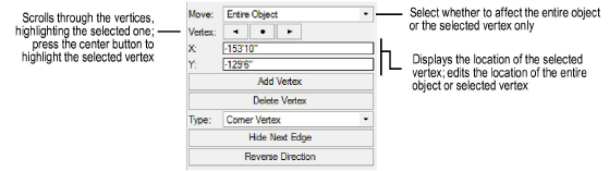
For vertex-based objects, functionality similar to the Reshape tool is available from the Object Info palette Shape tab, where values can be entered to move vertices (or the entire object) rather than manipulating them graphically with the tool. Similarly, click the buttons to add, delete, change the vertex type, or hide the next edge; the selected vertex is affected.
Use either the Selection tool or the Reshape tool from the Basic palette to select a vertex to edit. With the tool selected, Right-click (Windows) or Ctrl-click (Mac) on the vertex (if the SmartCursor is enabled, it snaps to each vertex and identifies the vertex type to assist with selection) and select Select Vertex in Object Info Palette from the context menu.
For certain vertex-based objects, you may first need to select the item and select an edit command to enter object editing mode. A colored border around the drawing window indicates editing mode is active (see Object Editing Mode).
The X and Y coordinates of the selected vertex display for editing in the Object Info palette.
~~~~~~~~~~~~~~~~~~~~~~~~~
Creating Layers
Creating Classes
The Object Info Palette
Using Arithmetic Expressions
2D Reshape Modes
The Object Info Palette: Data Tab
The Object Info Palette: Render Tab
Was
this page helpful?

vectorworks.net