Non-Uniform Rational B-Spline (NURBS) is a mathematical formulation that represents the geometry of curves, circles, arcs, and surfaces in 3D space. Free-form curves and surfaces can be created and edited with a high level of both flexibility and precision.
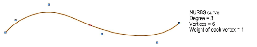
A NURBS curve generally consists of a degree value and weighted control points, or vertices. The curve passes between the vertex points; the degree determines how many points affect the curve. The direction indicates the starting and ending points of the curve as it was drawn, which can affect the outcome of certain operations.
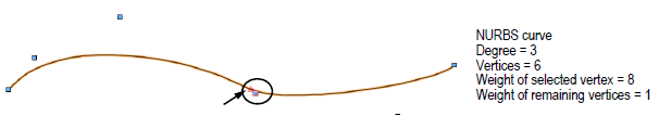
Increasing the relative weight of one of the vertices means the vertex has more of an influence on the curve and “pulls” the curve towards that vertex.
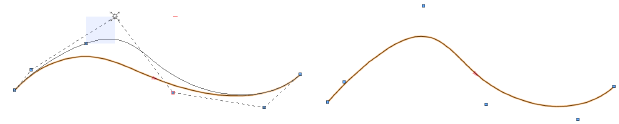
The Reshape tool can be used to move a vertex or several vertices, changing the shape of the curve (see Reshaping NURBS Curves).
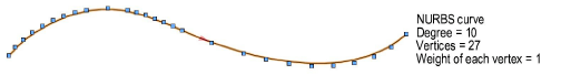
Increasing the degree of a NURBS curve proportionally increases the number of vertices, allowing for more flexibility in drawing the curve, but also more complexity due to the numerous weights affecting the curve.
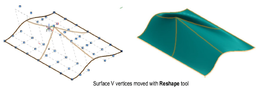
The same principles that apply to a NURBS curve apply to a surface. A NURBS surface is a grid, or mesh, of weighted control points in the U and V directions.
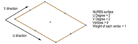
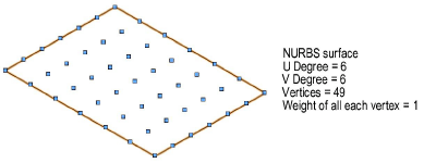
Increasing the degree of a NURBS surface in the U and/or V direction increases the number of vertices, adding flexibility as well as complexity.
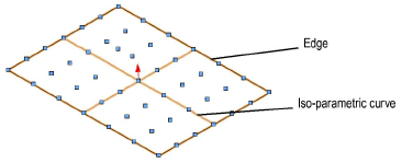
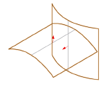
A NURBS surface also has a direction, or normal, which affects the outcome of certain operations, such as fillet surface creation. Iso-parametric curves indicate the U and V direction, and edge curves are drawn along the edges, helping to visualize the NURBS surface.
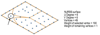
Each vertex on the surface can have a weight which “pulls” the surface towards the weighted vertices.
The Reshape tool can move a single vertex or a row of vertices, deforming the surface (see Reshaping NURBS Surfaces).
Both NURBS curves and surfaces can be defined by control points or by interpolation points. The curve or surface passes between control points or through interpolation points.
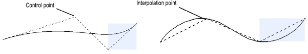
Interpolated curves and surfaces may be easier to modify. See Creating NURBS Curves and Interpolated NURBS Surfaces.
Complex, free-form shapes can be created with NURBS curves and NURBS surfaces. The shapes can then be combined, clipped, added to, trimmed, extended, analyzed, and otherwise modified as described in these sections.
The surface normal of NURBS surfaces can be displayed in order to clarify the surface direction and facilitate the creation of fillet surfaces (see Creating a Fillet Surface), shell solids (see Shell from a NURBS Surface), and the sectioning of solids (see Section Solids). In the Object Info palette, select Show Normal. The NURBS surface normal displays as a red arrow. Click Reverse Normal when a single NURBS surface is selected to reverse the direction of the surface normal. The arrow changes direction accordingly to indicate the new direction.
Click here for a video tip about this topic (internet access required).
~~~~~~~~~~~~~~~~~~~~~~~~~
![]()