 Creating
a Section Viewport on a Sheet LayerCreating
a Section Viewport on a Sheet Layer
Creating
a Section Viewport on a Sheet LayerCreating
a Section Viewport on a Sheet LayerWhen you create a section viewport, you can place it on either a sheet layer or design layer. Section viewports on sheet layers can have annotations and automatic drawing coordination of the sheet and drawing numbers; also, if there are multiple viewports on a sheet layer, each can a have different view and scale.
If you need to draw a detailed section, or to reference the section viewport into other files, create the viewport on a design layer instead. (See Creating a Section Viewport on a Design Layer.)
Create a section view from a design layer, from a clip cube, or from a viewport on a sheet layer. A section viewport that is created from a design layer or clip cube can be updated when changes are made to the design layer. However, a section viewport that is created from a viewport does not maintain a connection to the viewport that created it. It updates when the design layers that are visible in the source viewport change.
To create a section viewport on a sheet layer:
Prepare to create the viewport as follows:
● To create a section view from an active design layer, set the layer to Top/Plan view by selecting View > Standard Views > Top/Plan.
● To create a section view from an existing viewport, select a non-sectioned viewport object. The viewport object must be in Top, Bottom, Left, Right, Front, or Back view orientation.
● To create a section view from an existing clip cube object, use the Selection tool to highlight the face of the clip cube where the section will begin. (See Viewing a Model with the Clip Cube.) Right-click (Windows) or Ctrl-click (Mac) to open the context menu.
Select View > Create Section Viewport (for a design layer or viewport), or select Create Section Viewport from the context menu (for a clip cube).
Draw the section line to create the cutting plane on the design layer or viewport. For a clip cube, skip to step 4; the section line is created automatically from a vertical clip cube face, and no section line is created from a horizontal face.
Click in the drawing and drag the mouse to begin drawing the marker line. Click to mark the end of the line, and then click to indicate the side of the line to look toward (keep), which is indicated by a black arrow. Double-click to end the line.
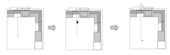
To create a broken section line, click in the drawing and draw the first segment. Indicate which side of the drawing to show in the viewport. Click and drag to draw additional segments; broken section line segments are always parallel or perpendicular to each other. Double-click to end the broken line.
The Create Section Viewport dialog box opens, set to the parameters of the active design layer or non-section viewport.
Click to show/hide the parameters.
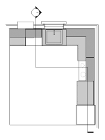
Click OK. A section line object is created in the design layer (unless you used a horizontal face of a clip cube), or is added to the annotations of the existing non-sectioned viewport. A section viewport is created on the selected sheet layer, and the drawing switches to that sheet layer, displaying the new section viewport.
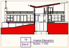
By default, the cross section areas (along the plane where the section was cut) are displayed in red. To change the fill color, or to display sectioned objects with their original attributes, change the viewport’s Advanced Properties (see Advanced Section Viewport Properties).
~~~~~~~~~~~~~~~~~~~~~~~~~
![]()