 Event Rigging and Structural AnalysisEvent Rigging and Structural Analysis
The design of rigging structures is an integral part of the event, entertainment, display, and exhibit industries. The Braceworks® suite of commands and tools inserts and connects supporting structures (such as trusses and lighting pipes), adds hoists and other supports, and then adds loads to the structures.
With a Braceworks license, the system uses the Finite Element Analysis (FEA) to accurately calculate and analyze the structural forces of a hanging rigging system, to determine whether the structural system is viable. Structural reports and the ability to export in DSTV format allow the calculations to be shared and validated by structural engineering colleagues.
|
|
Click here for a video tip about this topic (internet access required). |
 Braceworks-only Functionality
Vectorworks Spotlight incorporates many of the Braceworks features for drawing rigging structures and adding loads, allowing Spotlight users to take advantage of the rigging tools and run a system check (a Spotlight user may need to add the available commands to the workspace).
However, a Braceworks license is required to perform calculations and create reports.
The structural analysis calculations in Braceworks are done by an FEA core that performs calculations upon the rigging objects in the Vectorworks drawing (the truss, straight truss, curved truss, and lighting pipe). Each object is handled individually in the calculations; the FEA core considers all of the individual structural elements as beams. To determine the correct type of beam, each beam contains the cross section information required for proper calculations.
The following commands require a Braceworks license:
|
● Calculate All Objects |
● Create Calculation Report |
|
● Calculate Load Combinations |
● Braceworks Preferences |
|
● Calculate Visible |
● Calculation Overview |
|
● Calculate Selection |
● Cross Section Workload |
|
● Export DSTV |
● Scale Influence Lines |
In conjunction with Spotlight’s other tools and commands and features, lighting designers can use Braceworks tools as part of the design process, and rigging professionals can use the Braceworks tool set and commands to create, analyze, and report complete rigging designs. The suggested workflow will vary, depending upon the type of design, the venue, the event, and whether you have a Spotlight or Braceworks license.
Lighting designers planning to use Vision to previz the show can set up a file with Braceworks with little change to their current workflow. To reduce excess geometry, the use of the Straight Truss and Curved Truss tool as well as the Lighting Pipe tool is recommended. To keep lighting devices and other Spotlight design elements easier to work with, convert these truss and pipe items to hanging positions with the Convert to Hanging Position command.
● Collaborate with all departments involved with rigging elements.
● Specify the basics of the drawing, such as establishing the layer scale, creating layers, setting up Spotlight preferences, and so on. Create non-rigging elements for the drawing (stage objects, venue walls).
● Optional: Set up the truss inventory with the truss types and different truss lengths available, by selecting the Replace Truss command and clicking Truss Inventory.
● Braceworks required: Define the Braceworks Preferences.
● Create the rigging structure in the drawing space. Insert trusses with the Insert Truss tool. Auto Connect mode should be enabled so that the rigging elements create a system.
Alternatively, use the Straight Truss tool and/or the Curved Truss tool. Insert a lighting pipe with the Lighting Pipe tool. All of these elements are considered to be “beams” by Braceworks.
● If needed, add connections between structural elements. The Insert Connection tool creates hoists, dead hang objects, or truss cross connections between trusses.
● If bridles are needed, define the available rigging points with the Insert House Rigging Point tool, the Structural Member tool, and the Insert Mother Grid tool.
● Convert geometry with the Convert to Hanging Position command. This allows the structural objects to also function as hanging positions for Spotlight lighting devices and other Spotlight objects.
● If needed due to inventory restrictions or other requirements, replace parts of the truss line with different lengths of truss with the Replace Truss command, or replace one truss type with another with the Replace Truss Type command.
● Add, or have the various departments add, the load objects such as lights, speakers, video screens, and so on, or insert a point load or distributed load with the Insert Load tool. The auto-connect function snaps to the correct point. Loads are attached to hanging positions automatically, or can be added later. Any elements that are not needed for calculations (Braceworks required) should be kept on layers that are separate from the elements that will be calculated.
● Add hoists or dead hang objects to connect structural elements with the Insert Drop command, or use the Hoist tool and Insert Dead Hang tool to place drops that suspend the system.
Number the hoists so that they have unique IDs in reports and calculations.
● Insert bridles, and adjust their configurations, to support the truss system.
● Run the system check commands (first on selected, and then on all) to find any mistakes, such as unattached objects like loads or hoists, and misaligned or unsupported objects.
● Braceworks required: Correct any mistakes found. Braceworks provides color-coded annotations to assist with this, both in reports and within the drawing.
● Braceworks required: Hide the layers that do not participate in calculations, and then run the calculations first on a subset with the Calculate Selection command, and then on all visible items with the Calculate Visible command.
● Braceworks required: Make changes to the system as needed.
● Braceworks required: Run the calculations on all rigging items with the Calculate All Objects command to determine the viability of the system.
● Braceworks required: Make changes to the system as needed.
● Braceworks required: Create a report of the calculations.
● Braceworks required: Export reports if needed, sharing the data (PDF and/or DSTV file) with structural engineers, colleagues, or clients.
Braceworks calculations and, in some cases, functionality, depends upon creating connected rigging systems. As structural elements are placed in the drawing, they can automatically connect to other, similar elements with the same cross section, creating a system. Trusses, straight trusses, curved trusses, and lighting pipes can connect to form a system. Connected to those items, hoists, dead hang objects, and loads (including lighting devices, speakers, speaker arrays, video screens, soft goods, and generic point and distributed loads) are also considered to be part of the system, and they move or adjust with the system automatically.
It is important to use the method of Changing the Trim Height of a System to adjust the height of structural systems and all connected objects properly. All of the items in the system move together, and the hoists’ and dead hang objects’ chain lengths are automatically adjusted if needed.
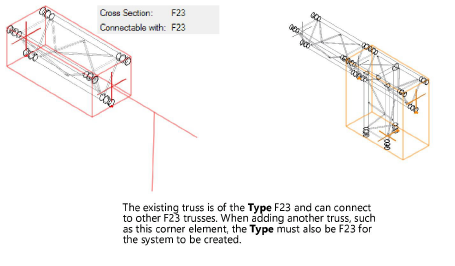
When drawing with the Insert Truss tool, ensure that Auto Connect mode is enabled so that truss systems are automatically connected. Only compatible trusses can connect automatically. If the truss to connect does not cause an existing truss to highlight, it is because they are not compatible, or one of the structural elements does not have a valid Connectable with parameter.
In Auto Connect mode, trusses can only connect to compatible connectors:
● Spigot and connector plates can connect freely.
● Gable can only connect to a fork.
● Spigot male can only connect to spigot female.
At insertion, Auto Connect mode automatically flips gable, fork, and spigot male/female trusses so that they connect properly. An alert opens only if a connection is not possible.
When adding other objects to the drawing, such as bridles, hoists, and loads, valid connected structural elements are highlighted in red, indicating that if placed there, the new object will connect to the system. Copying and pasting trusses, rigging objects, and even entire systems also use auto connect functionality to connect to existing systems.
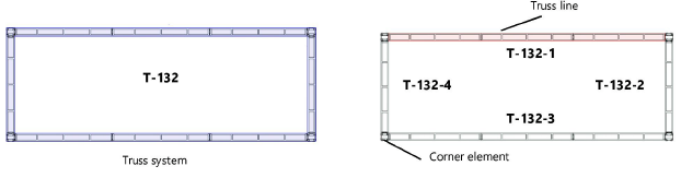
A completed rigging system consists of straight truss lines connected with corner elements to form a truss system, as shown in this simple illustration. Example naming of truss lines and the system is also shown; see Renaming Truss Systems for more information.
~~~~~~~~~~~~~~~~~~~~~~~~~
