Tool
Tool set
Shortcut
Callout

Basic
● Alt+1 (Windows)
● Option+1 (Mac)
Tool |
Tool set |
Shortcut |
Callout
|
Basic |
● Alt+1 (Windows) ● Option+1 (Mac) |
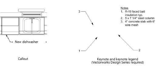
The Callout tool places callout objects to annotate items in a drawing. A callout object is a block of text attached to one or more leader lines with an optional bubble surrounding the text.
In the Vectorworks Design Series products, the Callout tool includes extended capabilities which allow it to be used for keynotes, and to connect the callout to an external notes database to place standard notes without retyping them each time they are used. If you use keynotes, a keynote legend is automatically created.

Mode |
Description |
Towards Target |
Click first where the callout text is to be placed, and place the final click on the object to be annotated |
Towards Text |
Click first on the object to be annotated, and place the final click where the callout text is to be placed |
Two Point |
The length of the shoulder is determined in the callout preferences or in the Object Info palette |
Three Point |
The length of the shoulder is determined by clicking in the drawing area; this requires an additional click. For example, if Max Leader Line Points is set to 2, three clicks are required to place the object with a custom shoulder length, and if Max Leader Line Points is set to 5, six clicks are required. |
Max Leader Line Points |
Enter the maximum number of leader line points for this callout object. If the object has multiple leader lines, each line can have a different number of points. Double-click to end a leader line that has fewer than the maximum allowed number of points. |
Preferences |
Opens the Callout Preferences dialog box |
To create a callout or (for Vectorworks Design Series products) a keynote:
1. Click the tool and then click Preferences.
2. The Callout Preferences dialog box opens. Specify the default settings for callouts or keynote objects during this session. You can also place a callout or keynote and edit these settings later from the Object Info palette, and make additional edits as described in Editing the callout.
 Click
to show/hide the parameters.
3. Click OK to set the callout or keynote preferences.
4. Click the applicable insertion modes, and then click in the drawing to set the insertion point of the callout or keynote object.
Depending on the mode, the first click defines the leader shoulder or the leader endpoint.

5. Continue clicking to set vertices and shape the leader line, as many times as permitted by the Max Leader Line Points value; double-click on the final point if this leader line requires fewer than the maximum number of points. The final click sets either the leader endpoint or leader shoulder, depending on the mode.
In Three Point mode, you can custom set the shoulder length by clicking in the drawing area; this requires one additional click.

After the final click, the Callout dialog box opens
6. See The Callout dialog box for information on how to specify the callout text, and then click OK.
The callout or keynote is placed in the drawing; if a keynote is placed, a keynote legend object is also created.

7. To add leader lines, and to set the attributes for the various parts of the callout object, use the Object Info palette, as described in Editing a callout object.
The Callout dialog box sets the callout or keynote text, whether manually entered or selected from a database (Vectorworks Design Series required for keynote and database options).
This dialog box is also named the Edit Callout dialog box or Edit Note dialog box, depending on how it is accessed; it uses the same parameters to edit the text for an existing note.
To set or edit the callout text:
Do one of the following:
● Place a callout object in the drawing as described in Inserting callouts or keynotes.
● Click Edit Note in the Object Info palette for a selected callout object.
The Callout dialog box opens.
 Click
to show/hide the parameters.
~~~~~~~~~~~~~~~~~~~~~~~~~