Inserting a video screen object Inserting a video screen object
 Tool |
Tool set |
Video Screen
|
Event Design |
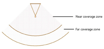
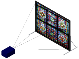
Video screen objects consist of a video screen and optional front or rear projector. The video screen and projector components can be independently placed on rigging objects (see Concept: Rigging objects).
If the screen and projector are both attached to rigging objects, only the attached video screen component is affected when its rigging object moves or rotates. If only the screen component is attached to a rigging object, the entire video screen object moves or rotates with the rigging object. If only the projector component is attached to a rigging object, only the projector moves or rotates with the rigging object.
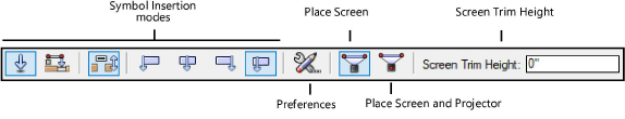
Mode |
Description |
Modes for the Symbol Insertion tool |
See The Symbol Insertion tool for parameter descriptions |
Preferences |
Sets the default properties for video screen objects |
Place Screen |
Places and rotates the screen and the projector at once; the projector’s location can be adjusted after placement |
Place Screen and Projector |
Places and rotates the screen and projector independent of each other |
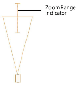
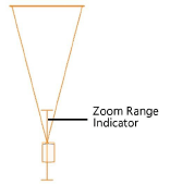
Screen Trim Height |
Sets the Z value of the screen at insertion |
|
Click here for a video tip about this topic (internet access required). |
To insert a video screen:
1. Click the tool and the symbol insertion and alignment modes.
2.Click the placement mode.
3.Enter the Screen Trim Height value on the Tool bar.
4.Insert the object in the drawing.
● In Place Screen mode, click to place the screen and projector, and click again to set the rotation.
● In Place Screen and Projector mode, click to place the screen, click again to set the screen rotation, and click again to place the projector. This is especially useful when placing video screens on rigging objects.
The first time you use the tool in a file, a properties dialog box opens. Set the default parameters. The parameters can be edited later from the Object Info palette.
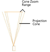
The height of the video screen and associated projector(s) depends on several factors.
● The Z value determines the distance from the active layer plane to the bottom of the screen (including the border).
● When the screen includes legs, the legs are drawn on the active layer plane unless a Floor Height value has been specified. The Floor Height distance shifts the floor, and therefore the legs, by that amount from the layer plane.
● Projector stands are inserted relative to both the Vertical Shift and Floor Height values, allowing stands to be shifted up or down from the screen’s floor as set by the Floor Height value.
● In Top/Plan view, when one of the video screen components, either the screen or the projector, is placed on a rigging object, that component assumes the height of the rigging object and associates with it. In a 3D view, the height is determined by the component’s insertion point on the rigging object. The Manage Loads tool allows precise repositioning of the video screen components; see Managing loads.
![]() Click
to show/hide the parameters.
Click
to show/hide the parameters.
~~~~~~~~~~~~~~~~~~~~~~~~~