 Inserting house
rigging pointsInserting house
rigging points
Inserting house
rigging pointsInserting house
rigging pointsTool |
Tool set |
House Rigging Point
|
Rigging |
House rigging points are defined early in the design process. They represent the fixed points in a venue where trusses, hoists, mother grids, and bridles can be inserted. Use the House Rigging Point tool to place house rigging points in the drawing.
Bridles can also snap to structural members, if the option to Use Structural Member as House Rigging Point is enabled from the Bridle preferences.
Mode |
Description |
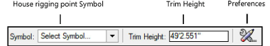
Symbol |
Opens a Resource Selector to select the house rigging point symbol; double-click a resource to activate it |
Trim Height |
Enter the Z height of the house rigging point |
Preferences |
Set the default parameters for house rigging points |
To insert a house rigging point:
1. Click the tool.
2.Click Preferences to open the object properties dialog box and specify the tool’s default parameters. The parameters can be edited later from the Object Info palette.
3.Click Symbol on the Tool bar to select a resource from the Resource Selector.
4.Enter the Trim Height of the house rigging point on the Tool bar.
5.Click to place the object in the drawing.
You can insert multiple house rigging points at once. To insert a house rigging point on several selected objects, see Inserting house rigging points automatically. To duplicate house rigging points, use the Duplicate Array and Duplicate Along Path commands; see Duplicate array and Duplicating objects along a path.
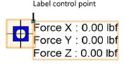
The house rigging point is inserted in the drawing, with a display of the forces in an associated label.
Click and drag the label control point to move the displayed forces. Select Text > Size to resize the text if needed.
6.Specify the Allowable Force X/Y/Z values on the Object Info palette to set the load limits of the rigging point.
![]() Click
to show/hide the parameters.
Click
to show/hide the parameters.
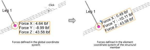
For structural engineering purposes, you can define the element coordinate system of a house rigging point. For example, rotate the Force X/Y/Z values for alignment to a structural member.
To define the element coordinate system:
1. Select one or more house rigging points.
2.Click Define ECS on the Object Info palette.
3.Click in the drawing to define the force orientation. For example, click on the centerline of a beam to define the forces in the beam direction.
Alternatively, use the Rotate tool to change the force orientation, or set the Rotation from the Object Info palette.
The forces are oriented in the specified direction. To calculate the forces, see Performing calculations (Braceworks required). If the forces were calculated previously, the calculation results automatically adjust to the new orientation.
~~~~~~~~~~~~~~~~~~~~~~~~~
