Tool
Tool set
Shortcut
Polyline

Basic
5
|
Tool |
Tool set |
Shortcut |
|
Polyline
|
Basic |
5 |
The Polyline tool creates open and closed polylines—objects made of a series of connected arcs, curves, or lines.
A polyline can consist of different combinations of vertices. While drawing a polyline, change the vertex type by selecting a different mode (or use the shortcut key (U by default) to switch modes; see Modifying special shortcuts). In Corner Vertex mode, press and hold the mouse to temporarily switch to Bézier Vertex mode. Press the Backspace key to remove the previously created vertex.
The corners of the polyline can be “smoothed” with the Poly Smoothing commands (see Smoothing objects). Markers can be added with the Attributes palette (see Marker attributes). The Push/Pull mode is available in 3D views for instantly extruding the polyline after creation.
|
|
Click here for a video tip about this topic (internet access required). |

|
Mode |
Description |
|
Corner Vertex |
Creates polyline segments with straight lines and angled vertices at the control points. The type of vertex created is a corner vertex. |
|
Bézier Vertex |
Creates polyline segments with curves pulled toward, but not touching, the control points. The type of vertex created is a Bézier vertex. |
|
Cubic Vertex |
Creates polyline segments with curves that pass through the control points. The type of vertex created is a cubic vertex. |
|
Tangent Arc |
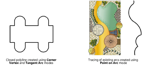
Creates polyline arc segments that are tangent to the previous segment (use tangent snapping to assist with drawing the tangent polyline; see Snap to tangent (2D Only)). The type of vertex created is a radius vertex. Enable Snap to Angle on the Snapping palette and use the Tangent SmartCursor cue to properly create a tangent arc polyline. |
|
Point on Arc |
Creates polyline arc segments that are drawn by clicking three points: the start point, a point the arc passes through, and the end point; useful for tracing existing arcs. The type of vertex created is a radius vertex. |
|
Arc Vertex Fillet |
Creates polyline segments with curves that look like a fillet placed at the control points; click Preferences to set the radius of the fillet. The type of vertex created is an arc vertex. |
|
Push/Pull (3D views only) |
Instantly extrudes the polyline after creation; see Push/Pull mode of planar tools |
|
Push/Pull Combine (available with Push/Pull mode) |
When the shape to be extruded is drawn on the face of a solid object, combines the two objects into a single solid addition or solid subtraction; when this submode is disabled, the new extrude remains a separate object, and the existing solid object remains unchanged |
|
Preferences |
Opens the Fillet Settings dialog box, to set the radius of the arc vertex fillet |
To create a polyline:
1. Click the tool and mode.
2.Click to set the polyline’s start point. In Point on Arc mode, click again to set a point that the arc will pass through.
3.Click to set the end of the segment and the beginning of the next.

4.Continue drawing segments in this manner until the polyline is complete.
5.Click the mouse at the start point to complete a closed polyline object (end point of the last segment is at the exact start point of the first segment), or double-click the mouse to complete an open polyline object (end point of the last segment is at a different location than the start point of the first segment).
Alternatively, after completing all but the final click, press the keyboard shortcut to automatically close the polyline. The shortcut also closes path-based objects, such as hardscapes and spaces, that function similarly to the Polyline tool. See Modifying special shortcuts to change the shortcut.
When drawing a polyline or path-based object, move the mouse in the direction of the next-to-last click and press the shortcut key before clicking; the software extrapolates the correct alignment and position for a 90 degree corner and places the final two clicks to complete the shape.
The resulting polyline object, whether open or closed, is a filled object. If desired, remove the fill through the Attributes palette to see objects behind the polyline.

Edit polylines, changing their shape or their vertices, with the Reshape tool or the Object Info palette (see Editing vertex-based objects). The corners of the polyline can be “smoothed” with the Poly Smoothing commands (see Smoothing objects). Markers can be added with the Attributes palette (see Marker attributes).
A closed polyline, when extruded with the Model > Extrude command, accepts a fill or texture and displays as a solid object. An open polyline, when extruded, does not render as a solid. To close a polyline before extruding it, select the polyline. In the Object Info palette, select the Closed option to close the polyline.
~~~~~~~~~~~~~~~~~~~~~~~~~