Editing the scene
The Scene Graph palette
|
Command |
Path |
Shortcut |
|
Scene Graph |
Window |
Ctrl+Shift+R (Windows) Cmd+Shift+R (Mac) |
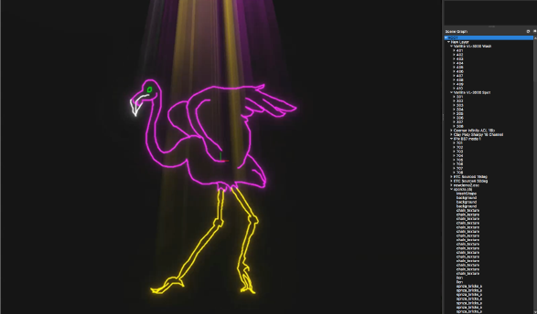
The Scene Graph palette displays an organized list of scene items, including layers, objects, and fixtures (lighting devices and lasers). Use the Scene Graph palette to select items in the scene, to select objects and fixtures for editing in the Properties palette, or to select conventional lighting devices for fine adjustments in the Software Console palette. The Scene Graph palette’s context menu provides options for organizing the scene contents, deleting items, replacing selected items, and troubleshooting display issues.
To open the Scene Graph palette:
Select the command.
The ROOT list heading, or “ROOT layer,” represents the contents of the entire scene; it contains a hierarchical list of layers, scene objects, and fixtures.
Merged scene files display as layers under the ROOT layer (see Merging files).
Click successive disclosure arrows to navigate the scene hierarchy. Press the Alt key (Windows) or the Option key (Mac) when clicking a disclosure arrow to expand or collapse all items in that layer.
Selected objects and fixtures are highlighted in the Scene window, and their parameters display in the Properties palette. When multiple items are selected, the displayed parameters depend on the first item selected; only that type of item displays parameters.
Selecting global scene parameters, objects, and fixtures
To select items, you may need to expand the layers in the Scene Graph palette:
From the Scene Graph palette, select ROOT to edit the global parameters for the entire scene (see Global parameters).
Expand the ROOT layer to access items within the scene. Use the Page Up/Page Down and arrow keys to scroll through the main ROOT layers. When a layer is selected, all items within the layer are also selected, so they can be moved and transformed as a group. These items are highlighted in the Scene window, and their parameters display in the Properties palette.
Exact parameter values display only if they are identical for all items in the layer. When a value differs, this is indicated by a double asterisk (**) after the parameter name, followed by a blank field or a value of 0.00.
Keep expanding the layers until you access an individual fixture or object, to select and edit only a single item. The selected fixture or object is highlighted in the Scene window, and its parameters display in the Properties palette. Lighting devices with accessories may also display parameters for gobo images and shutters in the Software Console palette. The displayed parameters depend on the lighting device type and accessories.
Multiple items can be selected by pressing the Shift key or the Ctrl (Windows) or Cmd (Mac) key while clicking on items in the Scene Graph palette.
Organizing the scene contents
|
Command |
Path |
|
Insert Layer |
Context menu |
To organize the scene contents, insert new layers in the Scene Graph palette. You can drag and drop items from one layer to another. When a layer is selected, all items contained in that layer are selected, so they can be moved and transformed as a group. This is especially helpful when setting up DMX transforms.
To insert a layer in the Scene Graph palette:
Select an item in the list of scene contents, and select the command.
A new layer is inserted into the selected layer, or into the layer of the selected fixture or object.
The layer can be renamed from the Properties palette.
To move a layer, click and drag it to the desired location. The ROOT layer is the highest level in the list of scene contents.
Correcting scene contents for previz
When objects are imported into Vision, they may need adjustment for correct display. The following commands apply only when certain options are selected in the document preferences.
Adjusting the normals
|
Command |
Path |
|
Invert Normals |
Context menu |
This command applies when Use Normals is selected on the Advanced: Rendering tab. If an object does not reflect light correctly, its normals might be invalid. To view the normals, select Render Normals from the Advanced: Rendering tab.
Left-facing normals are red.
Top-facing normals are green.
Front-facing normals are blue.
If an object’s normals are inverted, use the command to correct them.
To invert an object’s normals:
Select the object in the Scene Graph palette, and select the command.
Adjusting the winding order
|
Command |
Path |
|
Flip Winding Order |
Context menu |
When Use Face Culling is selected on the Advanced: Rendering tab, Vision uses a clockwise winding order to render the scene geometry. If any geometry displays incorrectly, its winding order might be incompatible.
Winding (in a clockwise or counter-clockwise direction) defines the order of a polygon’s vertices. The winding order determines which polygons are facing the camera. When the scene geometry is wound in the same direction, face culling can be used to render only the camera-facing geometry, for improved performance.
To reverse the winding order of one or more objects:
Select the object(s) in the Scene Graph palette, and select the command.
Refreshing the Scene Graph palette
|
Command |
Path |
|
Refresh |
Context menu |
You can refresh the Scene Graph palette to ensure the proper display of scene contents.
To refresh the Scene Graph palette:
Select the command.
The Scene Graph palette and the Properties palette are updated.