 Cables and power planning
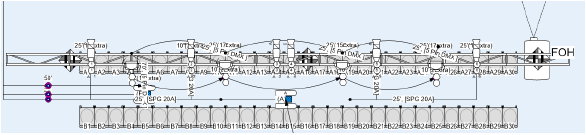
The cable and power planning features allow entertainment designers to model the power distributors and cabling for an event and to calculate the power requirements.
There are multiple ways to power patch electrical devices in the drawing. Cables can be drawn manually with the Cable tool, supporting 2D and 3D workflows. Cables can also be inserted automatically when patching by command or patching from the Object Info palette or the Power Planning palette. The Power Patch Table on the Power Planning palette provides an spreadsheet-type workflow for patching. The Power Planning palette also shows editable schematics of the electrical system and displays the power consumption data.
Once a cable run is placed in the drawing, you can reshape it or exchange the parts as needed. Create a report listing the cable parts required in different areas of the drawing. Cable objects are compatible with Braceworks, so the cable impacts on a system can be calculated seamlessly (Braceworks required).
Workflow: Power patching
Follow the suggested workflow when power patching the electrical system.
Model the venue space, including all the scene geometry, stage decks, and rigging. Add lighting devices and other electrical devices that require cables.
The device symbols in the drawing must support power planning. If the Object Info palette displays Power Information parameters, the selected device can be power patched.
If you are an advanced user, and the electrical device you need is not in the Vectorworks libraries, create a custom device symbol. Use the Electrical Component tool to place electrical components in the symbol definition.
Select Cable Preferences to define the insertion settings for cable objects and, optionally, select a cable set. If you would like to power patch devices without using the Cable tool, select the option to Automatically create cables between connected devices.
To use different preference settings in a specific part of the venue, use the Cable Area tool to draw a cable area. For example, cables on trusses may require additional slack than those placed at ground level.
Manage the cable inventory in the Vectorworks library and any user or workgroup files. Select Manage Cable Parts to specify the available parts and their properties.
Define the location of the venue's power sources.
Define the event's power distribution layout. Place the appropriate distributors (breakouts and/or plugboxes) on the trusses, located near the electrical devices that require power.
Draw commonly-used cable routes with the Cable Path tool.
Power patch the system by connecting the electrical devices (or by connecting the electrical components, if you create custom devices). There are several ways to power patch the system:
Use the Cable tool in Single Connection mode to place cables like feeder cables connecting the power supply to the power distribution racks and/or dimmer racks, or to place multi cables connecting dimmers and moving light distributors to breakouts. Use the Distributor or Schematic Distributor modes of the Cable tool to connect lighting devices and other electrical devices to the breakouts and/or plugboxes. From there, connect to the individual electrical devices that require the power. Use the Daisy Chain mode to connect multiple lighting devices or other electrical devices to a single circuit of a distributor (breakout or plugbox); click each device to connect in order. Cables can be automatically labeled with data tags according to the cable style.
Specify connections using the Power Information parameters on the electrical devices' Object Info palette (or the electrical components' Object Info palette, if you create custom devices).
Create connections automatically with the Power Patch Selected Objects command and the Power Patch Position command.
Use the Power Planning palette for patching. Connect devices from the Device Graph or, for an spreadsheet-type workflow, use the Power Patch Table.
If needed, adjust the cables with the Reshape tool or the Split tool, or change the cable configuration.
Label the cable paths and distributors with the Data Tag tool.
View the power calculation results from the Power Overview tab on the Power Planning palette. Print lists of the electrical loads in the drawing and the electrical workload for each power source.
Create loom and breakout worksheets listing the parts required for the venue.
