 Creating custom electrical devices
|
Tool |
Tool set |
|
Electrical Component
|
Lighting |
The Electrical Component tool and the Distributor tool share the same position in the Lighting tool set. Click and hold the mouse on the visible tool to open the Pop-out tools list and select the desired tool.
Electrical component objects are plug-in objects that define the internal components of an electrical device. They determine what type of connections the device can make so it can be power patched correctly within the electrical system. There are five types of electrical components: power sources, inputs, overcurrent protectors, outputs, and consumers. By using the Electrical Component tool to place component objects within a symbol definition, advanced users can create a custom electrical device that participates in power calculations.
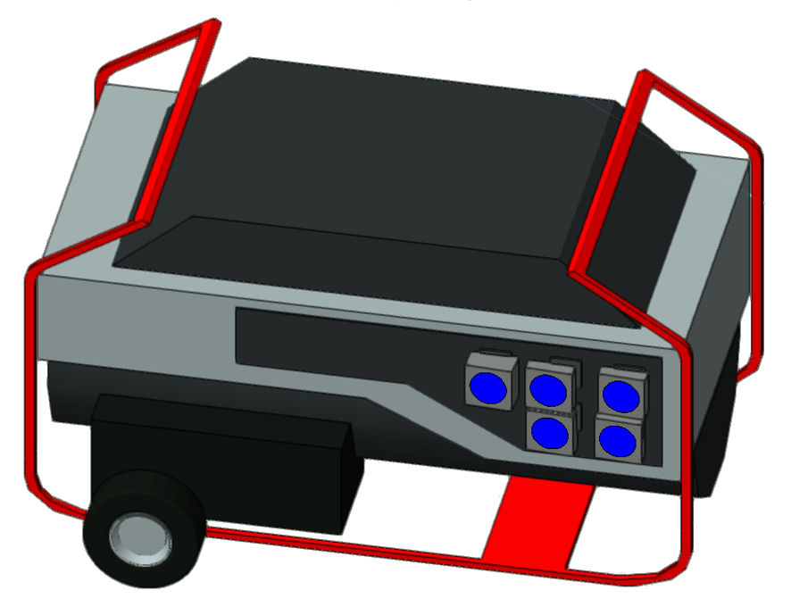
Custom distributor symbol with five output components
Electrical component objects define the internal wiring of an electrical device, which determines how the device symbol connects to other devices. Place electrical components inside the device symbol definition at the specific connection points. The visibility of the components is controlled by the Power class.
When a symbol contains an electrical component object, Power Information parameters display on the symbol's Object Info palette to enable power patching; see Power patching from the Object Info palette for more information. The order of the input and output fields is determined by the electrical components' stacking order; see Changing object stacking order. The distributor and lighting device symbols in the Vectorworks libraries are pre-defined electrical devices, so they display Power Information parameters by default.
Pay special attention when naming an electrical component. This name identifies the component in the container device's Object Info palette and in the Power Planning palette. If a name is not provided, a generic name is assigned with an incrementing number. For example, if a distributor with an ID of DistroA has two output sockets, the device symbol requires two output components. By default, these will be named Output and Output 1. The components will display as DistroA.Output and DistroA.Output1 in the Power Patch Table.
![]()
|
Mode |
Description |
|
Power Source
|
Places a power source electrical component
|
|
Input
|
Places an input electrical component
|
|
Overcurrent Protector
|
Places an overcurrent protector electrical component
|
|
Output
|
Places an output electrical component
|
|
Consumer
|
Places a consumer electrical component
|
Placing a power source component
|
Mode |
Tool |
Tool set |
|
Power Source
|
Electrical Component
|
Lighting |
A power source component enables a device to generate power.
When a power source component is placed in a custom electrical device symbol, it generates an output field on the Object Info palette of the device. When power patching the device, this output can be connected to another device's input; multiple connections can be made. See Power patching from the Object Info palette.
The power source component cannot be power patched from its Object Info palette.
To place a power source component in a symbol definition:
Select a symbol instance in the drawing, and select Edit 3D Component from the context menu.
Alternatively, right-click on the symbol in the Resource Manager, and select Edit 3D Component from the context menu.
The symbol's 3D component displays in Object editing mode.
Click the tool and mode.
Place the component in the desired location.
Set the parameters on the Object Info palette.
Click to show/hide the parameters.Click to show/hide the parameters.
|
Parameter |
Description |
|
Rotation |
Rotates the component |
|
Name |
Enter a name for the component. This name is globally used for power patching, with the container device's ID prepended. For example, Distrib1.GeneratorOut1. |
|
Scale X/Y |
Scales the component geometry. The default size is 10 cm x 10 cm x 10 cm. |
|
2D Part X/Y |
Sets the X/Y coordinate position of the component's 2D geometry |
|
Connector |
Select the connector for the component |
|
Maximum Power |
Displays the maximum power in amps per phase of the power source |
|
Voltage |
Displays the voltage per phase of the power source |
Click Exit Symbol to return to the drawing. An output field displays on the Object Info palette of the symbol, which now functions as a patchable electrical device. The output field is labeled with the component Name.
Placing an input component
|
Mode |
Tool |
Tool set |
|
Electrical Input
|
Electrical Component
|
Lighting |
An input component enables a device to receive power.
When an input component is placed in a custom electrical device symbol, it generates an Input field on the Object Info palette of the device. When power patching the device, this input can be connected to another device's output; a single connection can be made.
The input component can also be power patched from its Object Info palette. Each socket of the input component can be connected to an output socket or an overcurrent protector in-socket. See Power patching from the Object Info palette.
To place an input component in a symbol definition:
Select a symbol instance in the drawing, and select Edit 3D Component from the context menu.
Alternatively, right-click on the symbol in the Resource Manager, and select Edit 3D Component from the context menu.
The symbol's 3D component displays in Object editing mode.
Click the tool and mode.
Place the component in the desired location.
Set the parameters on the Object Info palette.
Click to show/hide the parameters.Click to show/hide the parameters.
|
Parameter |
Description |
|
Rotation |
Rotates the component |
|
Name |
Enter a name for the component. This name is globally used for power patching, with the container device's ID prepended. For example, Breakout1.Input1. |
|
Scale X/Y |
Scales the component geometry. The default size is 10 cm x 10 cm x 10 cm. |
|
2D Part X/Y |
Sets the X/Y coordinate position of the component's 2D geometry |
|
Connector |
Select the connector for the component. The selection determines which socket fields display below. |
|
Sockets |
Specify each socket connection from the list of available options, defined by the Connector |
Click Exit Symbol to return to the drawing. An input field displays on the Object Info palette of the symbol, which now functions as a patchable electrical device. The input field is labeled with the component Name.
Placing an overcurrent protector component
|
Mode |
Tool |
Tool set |
|
Overcurrent Protector
|
Electrical Component
|
Lighting |
An overcurrent protector component defines the breakers (of the type MCB: miniature circuit breakers) that limit the current running through the wires of a device.
The overcurrent protector component can be power patched from its Object Info palette. The sockets of an overcurrent protector component can be connected to an output socket or an input socket. See Power patching from the Object Info palette.
An overcurrent protector component does not enable connections from the container device's Object Info palette or the Device Graph on the Power Planning palette.
To place an overcurrent protector component in a symbol definition:
Select a symbol instance in the drawing, and select Edit 3D Component from the context menu.
Alternatively, right-click on the symbol in the Resource Manager, and select Edit 3D Component from the context menu.
The symbol's 3D component displays in Object editing mode.
Click the tool and mode.
Place the component in the desired location.
Set the parameters on the Object Info palette.
Click to show/hide the parameters.Click to show/hide the parameters.
|
Parameter |
Description |
|
Rotation |
Rotates the component |
|
Name |
Enter a name for the component. This name is globally used for power patching, with the container device's ID prepended. For example, Distrib1.Fuse1. |
|
Scale X/Y |
Scales the component geometry. The default size is 10 cm x 10 cm x 10 cm. |
|
2D Part X/Y |
Sets the X/Y coordinate position of the component's 2D geometry |
|
Rating |
Displays the type and sensitivity of the overcurrent protector |
|
Ampere |
Sets the breaker amperage of the overcurrent protector |
|
In |
Select the in-socket connection from the list of available options |
|
Out |
Select the out-socket connection from the list of available options |
Click Exit Symbol to return to the drawing. The component does not generate Power Information fields on the Object Info palette.
Placing an output component
|
Mode |
Tool |
Tool set |
|
Electrical Output
|
Electrical Component
|
Lighting |
An output component enables a device to transfer power.
When an output component is placed in a custom electrical device symbol, it generates an Output field on the Object Info palette of the device. When power patching the device, this output can be connected to another device's input; multiple connections can be made.
The output component can also be power patched from its Object Info palette. Each socket of the output component can be connected to an input socket or an overcurrent protector out-socket. See Power patching from the Object Info palette.
To place an output component in a symbol definition:
Select a symbol instance in the drawing, and select Edit 3D Component from the context menu.
Alternatively, right-click on the symbol in the Resource Manager, and select Edit 3D Component from the context menu.
The symbol's 3D component displays in Object editing mode.
Click the tool and mode.
Place the component in the desired location.
Set the parameters on the Object Info palette.
Click to show/hide the parameters.Click to show/hide the parameters.
|
Parameter |
Description |
|
Rotation |
Rotates the component |
|
Name |
Enter a name for the component. This name is globally used for power patching, with the container device's ID prepended. For example, Breakout1.Output1. |
|
Scale X/Y |
Scales the component geometry. The default size is 10 cm x 10 cm x 10 cm. |
|
2D Part X/Y |
Sets the X/Y coordinate position of the component's 2D geometry |
|
Connector |
Select the connector for the component. The selection determines which socket fields display below. |
|
Sockets |
Specify each socket connection from the list of available options, defined by the Connector |
Click Exit Symbol to return to the drawing. An output field displays on the Object Info palette of the symbol, which now functions as a patchable electrical device. The output field is labeled with the component Name.
Placing a consumer component
|
Mode |
Tool |
Tool set |
|
Consumer
|
Electrical Component
|
Lighting |
A consumer component defines a device as a power consumer.
When a consumer component is placed in a custom electrical device symbol, it generates an input field on the Object Info palette of the device. When power patching the device, this input can be connected to another device's output; a single connection can be made. See Power patching from the Object Info palette.
The consumer component cannot be power patched from its Object Info palette.
To place a consumer component in a symbol definition:
Select a symbol instance in the drawing, and select Edit 3D Component from the context menu.
Alternatively, right-click on the symbol in the Resource Manager, and select Edit 3D Component from the context menu.
The symbol's 3D component displays in Object editing mode.
Click the tool and mode.
Place the component in the desired location.
Set the parameters on the Object Info palette.
Click to show/hide the parameters.Click to show/hide the parameters.
|
Parameter |
Description |
|
Rotation |
Rotates the component |
|
Name |
Enter a name for the component. This name is globally used for power patching, with the container device's ID prepended. For example, LightDev1.PowerColorScroller. |
|
Scale X/Y |
Scales the component geometry. The default size is 10 cm x 10 cm x 10 cm. |
|
2D Part X/Y |
Sets the X/Y coordinate position of the component's 2D geometry |
|
Connector |
Select the connector for the component |
|
Power |
Sets the amount of power used by the device (its electrical load) |
|
Power Factor |
Sets the power factor for the device (this is the ratio of working power to apparent power; devices with a low power factor are less efficient) |
|
Maximum/Minimum Voltage |
Sets the minimum and maximum voltage at which the device can operate |
Click Exit Symbol to return to the drawing. An input field displays on the Object Info palette of the symbol, which now functions as a patchable electrical device. The input field is labeled with the component Name.
