Creating valleys on a slab
|
Mode |
Tool |
Tool set |
|
Create Valley
|
Slab Drainage
|
Building Shell |


Slope valleys, which connect a drain to the slab edge, are formed by the intersection of two slab planes; the planes are indicated by slope markers. A slope valley’s end height is computed based on the drain height and the intersection with the slab edge. Valley ends are important because they are places where the curb changes slope. Valleys must end in corners of the perimeter if the user desires a curb of uniform height.
To create slope valleys on a slab:
Select the slab object.
Click the tool.
Click Settings on the Tool bar to open the Slab Drainage Settings dialog box and specify the default settings for this slab (see Slab drainage settings). Some of these individual settings can be edited later using the Slab Drainage tool’s Edit mode (see Editing slab drainage elements).
Click the mode.
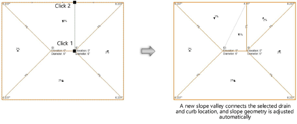
Click on a drain to start the valley; a new valley line is previewed. Click a second time to place the valley’s control point. If the control point is not located on a slab edge, the valley is automatically extended to the intersecting edge.
The new valley splits the existing slab slope in that direction into two slab slopes, and existing valleys are automatically changed as necessary for the new geometry. No valley can be added within five degrees of any other slope valley associated with the same drain. If the attempted valley placement is impossible given the slab’s geometry, nothing is drawn.