Creating site model components
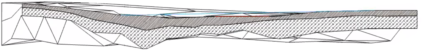
Site model components define the sections that make up a site model beneath the surface. For example, to indicate that a site model is made up of manufactured and geological layers (such as mulch, gravel, soil, bedrock, etc.) define a component for each of these items to illustrate their location and thickness. Components are created as 3D meshes. Component appearance, as well as the specific thickness of a location at a survey point location, can be specified for cross-section views (section viewports), and they can be textured, creating realistic section views and rendered views. If a material resource is used to define a component, the material typically provides the fill, texture, physical attributes, and construction information needed for drawings, renderings, and reports.
The overall thickness of a site model is equal to the sum of its components. Component fill and pen style are only displayed in section viewports.
Use the Eyedropper tool to copy site model component settings from one site model to another (see Transferring attributes).
To define site model components:
Do one of the following:
To define a component while a site model is being created, or to add components to an existing site model without components enabled, click on the Components pane of the Site Model Settings dialog box. Select Enable components below surface, and then click Edit Components.
To edit or add components for an existing site model with components enabled, select the site model and click Edit Components on the Object Info palette to open the site model Components dialog box. Alternatively, select the site model, select the Edit context menu command, and click Components from the Edit Site Model dialog box.
The Site Model Components dialog box opens.
Click to show/hide the parameters.Click to show/hide the parameters.
|
Parameter |
Description |
|
Preview |
Displays a sectioned preview of the site model, including any defined components. |
|
Overall Thickness |
Displays the thickness of the site model. The site model thickness is always determined by the thickness of its components; a site model always has one component by default. |
|
Datum |
The datum does not apply to site models |
|
Surface |
The surface does not apply to site models; all components have a fixed thickness unless you specify thicknesses as described in Adjusting component thickness with survey points |
|
Components |
Lists the components that form the site model, in order from top to bottom as displayed in the preview. To change the order of a component, click and drag within the # column. If multiple components are selected, changing the order moves all selected components to the new location. |
|
Datum |
The datum does not apply to site models |
|
Tapered |
Site model components cannot be tapered |
|
Other Component settings |
The remaining columns in the component list display the current settings for the site model, from the Site Model Component Settings dialog box. |
|
New |
Opens the Site Model Component Settings dialog box to define the components of the site model |
|
Edit |
Opens the Site Model Component Settings dialog box to edit the attributes of one or more selected components; changes are made to all selected components. Alternatively, to edit a single component, double-click the component to open the Site Model Component Settings dialog box. |
|
Duplicate |
Duplicates one or more selected site model components; the duplicates are added to the component list right below the originally selected components |
|
Delete |
Deletes one or more selected site model components; the site model thickness is adjusted accordingly |
Below the Components list, click New to create a new component (or select a component to edit and click Edit).
The Site Model Component Settings dialog box opens. Specify the component thickness, name, and parameters.
Click to show/hide the parameters.Click to show/hide the parameters.
|
Parameter |
Description |
|
Definition |
|
|
Name |
Provide a name for the component, which displays in the Components list in the Site Model Components dialog box |
|
Class |
To control appearance and visibility, select a class from the list of classes present in the drawing, or create a new class. Select <Object Class> to place the component attributes in the same class as the site model object. |
|
Use material |
Uses a material resource for this component; select a material from the Resource Selector. |
|
Thickness |
Specifies the component’s default thickness; the thickness of a site model is the sum of its components. A component must have a thickness greater than 0. The thickness of a component can be set to vary depending on location, as described below. |
|
Section Fill |
Specifies the component appearance in section views. If the component uses a material, the fill is set to the material’s fill, and the controls are disabled. Otherwise, select a fill style, or Class Style to set the fill attributes by class. Depending on the Style selected, select a color, pattern, or resource (hatch, image, gradient, tile). |
|
Section Pen |
Specifies the component appearance in section views. Select a pen style, or Class Style to set pen attributes by class. Depending on the Style selected, select a color, pattern, or line type resource. |
|
Thickness |
Select the line thickness; to use a custom thickness, select Set Thickness from the line thickness list (see Line thickness attributes) |
|
Texture |
Applies the selected texture to the component. If the component uses a material, the texture is initially set to the material’s texture, but this can be overridden. Class Texture sets the component to use the texture specified by the component’s class; see Concept: Applying textures by class. If Texture is chosen, this setting overrides the object material and/or class texture; select a texture from the Resource Selector. The Object Info palette Render tab has additional texturing controls for existing objects; see Managing object textures from the Object Info palette and Textures on objects with components. Textures applied from the Object Info palette override the textures set here unless the texture is set by style. |
|
Make All Attributes By Class |
Sets all fill, pen, and texture attributes by class, except those that come from a material |
|
Remove By Class Settings |
Removes all class settings for fill, pen, and texture attributes; does not affect material definitions with attributes set by class |
After you click OK, the site model’s Overall Thickness value changes to be determined by its components. As components are defined, they display in the preview. Click and drag a component in the # column to change its order.
Adjusting component thickness with survey points
|
Tool |
Tool set |
|
Add Survey Points
|
Geological Survey Edit |
Thickness data can be adjusted for each created component for different locations. Once the components have been defined for a site model, the Add Survey Points tool can edit the thickness of the components based on survey data point locations. The volume of components can be reported in worksheets.
Components cannot be added or removed by this process; add or remove components in the Site Model Components dialog box (you can remove a component by setting the thickness of the component to 0 (zero) if needed).
![]()
|
Mode |
Description |
|
Insert
|
Inserts a survey point with the default component thickness |
|
Pickup
|
Copies the component thicknesses of an existing survey point, making it the default for component thickness values; the existing point is highlighted for reference |
|
Paste
|
Pastes the default component thickness to an existing survey point |
|
Import File
|
Imports a survey file; select the file to import. A set of survey points is created, with one point for each row in the survey file. |
|
Preferences
|
Sets the default thicknesses for the components defined for the site model |
To adjust component thickness:
From the Object Info palette of a selected site model, click Edit Geological Survey Points.
Alternatively, select the site model, select the Edit context menu command, and then click Geological Survey Points from the Edit Site Model dialog box, or click Edit Geological Survey Points from the Site Model Settings dialog box (the latter is only available after the site model has been created, and does not appear when creating a site model).
In survey edit mode, available tools display in a special Geological Survey Edit palette. This palette is only available within the geological survey edit mode.
Click the tool.
Do one of the following:
Import a set of survey points in Import File mode. Select the file of survey points to import.
Place a single survey point in Insert mode.
To set the default thickness of the site model components, click Preferences mode.
The Add Survey Point Preferences dialog box opens, listing the components present in the site model, the default thickness for each, and the elevation. When an existing survey point is selected, the default thickness can be edited in Select Component Thickness. If a different default thickness is selected with Pickup mode, these default values change.
To pick up default component thicknesses from an existing survey point, click Pickup mode.
To paste default component thicknesses, changing the component thicknesses at that point, click on an existing survey point in Paste mode.
Place survey points either by importing or inserting them, and then adjust the thickness of the components at those points in the Object Info palette (or by using Pickup and Paste mode).
The Object Info palette displays the current thickness of each component defined for the site model. Adjust the thickness at that location as needed.
When the components have been adjusted, click the Exit Site Model Geological Survey Points (or select the identically-named command from the Modify menu) to apply the changes and return to the drawing.
The component edits are applied to the site model. The site model uses the components and the geological survey points to generate approximate elevation changes for the components. Section viewports can then display the correct visuals for the geological layers at the section line, and components can be reported in worksheets.