 Space settings
Use the Space tool’s Preferences to set the default parameters for space objects before you create them, including the label style, automatic numbering, boundary calculations, and graphic attributes. To control the display of spaces, you can set default classes for the label, label leader line, graphic attributes, and the entire space object. Preference settings are an easy way to apply common, consistent settings to all spaces.
The space’s 2D graphic attributes are not taken from the Preferences settings. Instead, set the appropriate fill and pen styles in the Attributes palette before you create the spaces.
You can create plug-in objects with a combination of parameters that are determined by the manufacturer’s catalog item, by style and/or by instance, and then optionally save them as a plug-in object style. Style parameters have a fixed value established by the style; instance parameters can be set independently for each instance of the object in the drawing (see Concept: Plug-in object styles).
Once the spaces have been created, use the Object Info palette to edit the properties of individual spaces, including space name and occupant, room finishes, and any additional data attached to the space. To access the full set of space properties, click the Settings button to open the Space Settings dialog box.
The properties that are available from the Object Info palette are determined by the Advanced Settings pane on the Space Settings dialog box. See Space settings: Advanced Settings pane for details.
To reduce the time required to regenerate space objects after properties are edited, Vectorworks only regenerates the space components that are changing and only recalculates the bounds of the spaces if necessary. To force the complete regeneration of edited space objects, select Tools > Utilities > Reset All Plug-Ins.
The settings are grouped into several panes of related parameters. Select each group of parameters from the list in the left pane of the dialog box; the parameters are displayed in the center pane.
The right pane of the dialog box always displays a preview of the space label based on the current settings. To edit the appearance of any of the space labels (for example, to change the font size or the pen color), click the label’s Edit Layout button at any time.
A few controls can be edited directly from the Object Info palette, as described in Space properties.
Space settings
Click to show/hide the parameters.Click to show/hide the parameters.
|
Parameter |
Description |
|
Style |
To create a custom space, leave the Unstyled setting. To use an existing space style from the resource libraries, click Style; from the Resource Selector, double-click a resource to activate it. |
|
Convert to Unstyled |
If a Style is currently set, select this option to convert the object to unstyled; the current values are retained, but all parameters on all panes are set to By Instance to allow editing |
|
By Style/Instance |
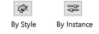
A graphic indicates whether each parameter is set to By Style and given a fixed value by the user or set to By Instance and editable in the dialog box. An object style may have a combination of both settings, to balance the need for consistency and flexibility. By Style/Instance settings are established by the style and cannot be changed from the settings dialog box.
To edit the object style, see Editing plug-in object styles; editing the style modifies all plug-in objects in the file that use the style. |
|
Space Label Preview |
Displays a preview of the space label with the currently selected parameters; see Space settings: Space Label 1, 2, and 3 panes. Space Label 1 previews by default. Space Label 2 and Space Label 3 preview only if Enable multiple labels is selected on the Advanced settings pane and Display Space Label is selected on the Space Label 2/3 pane. |
|
Edit Layout |
Click to enter object editing mode to edit the format of the specified label; see Object editing mode |
Space settings: Numbering pane
Click to show/hide the parameters.Click to show/hide the parameters.
|
Parameter |
Description |
|
Space Number |
Displays the space number based on the current settings on the pane and cannot be edited |
|
Space Number Type |
Specifies the type of numbering to use on space objects. Label Text: The text in the Label Text field is the space number. Incrementing Value: Automatically assigns the next available number, according to the Incrementing Value settings. Custom combinations: The space number is a combination of items, and can include an incrementing value, space-related variables, and/or static text. Combinations you create display below the Incrementing Value option on the list. Edit Combinations: Opens a dialog box to create or edit combination number types; see Custom number types. |
|
Label Text |
Label Text functionality depends on the Space Number Type setting: Label Text: Specifies text to be stored as both the space number label text and space number; the text can be edited from the Object Info palette or worksheets Incrementing Value: The space number is a simple incrementing value, so the Label Text field is not available Combination type: Specifies text that can be used in a space number combination |
|
Incrementing Value |
These can be integers (1, 2, 3 ...), or upper or lower case letters (A, B ... Z, AA, AB, AC ...). When editing a space, you can set this value directly. When setting space preferences, specify the following: Start value: Value to assign to the first new space Increment: Amount to increment the value of each new space Next value: Value to assign to the next new space that is created |
|
Manage |
When editing a space, opens a dialog box to adjust the automatic space numbers; see Manage Sequence dialog box |
Space settings: Occupancy pane
Click to show/hide the parameters.Click to show/hide the parameters.
|
Parameter |
Description |
|
Space Type |
Identifies a space as either Normal (for example, a room) or Full Floor (the entire floor of a building) |
|
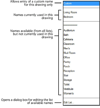
Space Name |
Specifies the space name; the spaces in an adjacency matrix are listed by space name, and the space name can also be used in space labels. Select a name from the list, or select Custom and enter a name in the field below the pull-down list. The top portion of the list contains the space names that are currently used in the drawing. The lower portion of the list displays all available space names that are still unused, compiled from lists in the Vectorworks program folder, your user folder, and your designated workgroup folder. To customize a space name list, select Edit List from the bottom of the list to open the Edit Space - Space Name List dialog box. See Editing lists of space names and occupant organizations.
|
|
Occupant Type |
Specifies the occupant type (owner, tenant, lessee, and so on). Select a type from the list, or select USERDEFINED and enter a name in the field below the pull-down list. |
|
Occup. Organization |
Specifies the organization associated with the occupant; the spaces in the stacking diagram are grouped by the organization name. This field is very similar to the Space Name field above. The list is separated into sections based on whether the available names are currently in use. Select a name from the list, or select Custom and enter a name in the field below the pull-down list. To customize an occupant organization list, select Edit List from the bottom of the list to open the Edit Space - Occ Organization List dialog box. |
|
Occupant Name |
Specifies the individual occupant name |
|
Proposed Area |
Specifies the programmed area for the space |
|
Click the column to the left of a zone name to select it. Up to five zones of different types can be assigned to a space; only one zone can be assigned from each zone type (HVAC, Preservation, Security, and so on). When you edit a space from the Object Info palette, click the Assign Zones button to open a dialog box with the same zone information that displays on the Occupancy pane. To customize the zones list, click New to open the Create Zone dialog box. To add a zone to an existing zone type, select the Zone Type, enter the Zone Name. To create a new zone type, select Add New Zone Type from the Zone Type list, enter a name. To delete a zone, click the zone name, and click Delete to remove the zone from the list. The IFC Zones, Systems and Group command attaches IFC data to space zones. See Assigning IFC data to zones, systems, and groups. |
|
|
GSA Occupancy |
If Enable GSA is selected (Advanced Settings pane), opens the GSA Occupancy dialog box to enter the data required for GSA projects (see GSA data). When the drawing is complete, select File > Export > Export IFC Project to save the file in IFC format. |
Space settings: 2D Boundaries and Area pane
Many parameters on this pane are available only if the space is connected to adjacent walls.
Click to show/hide the parameters.Click to show/hide the parameters.
|
Parameter |
Description |
|
Boundary Display |
|
|
Show 2D boundary |
Displays the polyline that represents the space; if this option is selected, also select an option for the 2D Boundary Display. |
|
2D Boundary Display |
Specifies what to display for the space: Inside Walls less Columns, Inside Wall Faces, Wall Centerlines, Net Boundary, or Gross Boundary. A Net boundary is defined by the inside face of the surrounding walls; the Gross boundary display is defined by the Gross Boundary Def. setting. If the area and perimeter values for the space are used in a worksheet, the values always match the displayed boundary. |
|
Net Boundary |
|
|
Offset from Inner Faces of Walls |
Enter the desired offset, if any, from the inner faces of the walls when calculating the space net boundary |
|
Consider wall projections and recesses |
When selected, wall projections and recesses modify the perimeter of the space net boundary |
|
Consider column “islands” |
When selected, each column reduces the area of the space net boundary |
|
Consider door and window niches |
When selected, the niches defined by doors and windows modify the perimeter of the space net boundary. Door and window niches are included in the area calculation only for door/window instances with Create Niche for Space Objects selected on the General pane of the Door Settings or Window Settings dialog box. |
|
Gross Boundary |
|
|
Gross Boundary Def. |
Specifies the definition to use for the gross boundary: Wall Centerlines, Building Gross, Outer Wall Core, Center Wall Core, BOMA Rentable, or Custom. If Building Gross is selected, auto-bounded space objects automatically detect whether the bounding walls are interior walls or exterior walls and update the Gross Area calculation. Exterior walls are those that have Exterior selected on the Data pane of the Wall Preferences dialog box. For exterior walls, the gross space area is measured to the outside of the wall. For interior walls, the gross space area is measured to the wall centerline. If Outer Wall Core or Center Wall Core is selected but the wall has no core component, the space boundary is defined by the outer edge or center, respectively, of the entire wall. The Custom option is only available for an existing space object surrounded by walls. |
|
If the Gross Boundary Def. is set to Custom, click to open the Edit Custom Gross Boundary dialog box. Do one of the following: Select each wall in the display window, and then select the appropriate bounding definition for it. Click Reset Gross Boundary to set all boundaries for the space to one of five pre-set options (Centerlines of All Walls; Centerlines of Interior Walls, Outer Core Component of Exterior Walls; Centerlines of Interior Walls, Center Core Component of Exterior Walls; Centerlines of Interior Walls, Inside Face of Exterior Walls; Centerlines of Interior Walls, Outside Face of Exterior Walls). |
|
|
Area Calculation |
|
|
Net Area Modifier (%) |
Adjusts the net area value by the specified percentage |
|
Gross Area Modifier (%) |
Adjusts the gross area value by the specified percentage |
|
Room Dimensions |
|
|
Calculate room dimensions |
Automatically calculates the Length and Width dimensions of the space object; when deselected, the Length and Width can be entered manually |
|
Length/Width |
Displays the dimensions of the space; when Calculate room dimensions is deselected, the Length and Width can be entered manually. Manual changes affect the display of the length and width values, but do not change the actual dimensions of the space object. |
|
Opens the Additional Area Settings dialog box to define how much area to subtract from the calculation for spaces that have low ceilings. These settings apply to all 2D and 3D spaces in the document. For the Subtraction Area 2D (document-wide) section, set up to four subtraction category percentages to display as options when Modifying the area of 2D spaces with the Add Area Modifier to Space command. For the Area Subtractions under Low Ceiling (document wide) section, enter subtraction settings for up to two height ranges. For each range, click Enable first/second area subtraction, and enter the following: If Height Less Than: The height threshold below which area will be subtracted. Subtraction (%): The percentage by which area will be reduced for this height range. Create contour line: Creates a contour line that shows the border between the different height ranges. Set the line’s attributes on the Graphic Attributes pane. |
Space settings: 3D Boundaries pane
Click to show/hide the parameters.Click to show/hide the parameters.
|
Parameter |
Description |
|
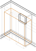
Show 3D |
Displays the space volume boundaries in 3D
|
|
Volume Display |
Select whether to display the Net or Gross volume; the actual net or gross volume depends on the height boundary selections and any offsets |
|
Height Net / Gross |
|
|
Height |
Directly sets the desired net or gross height of the space. When the space height is determined manually by this method, the Top Bound property of the space is automatically set to Layer Elevation, and the Top Offset value is modified accordingly. When the top of the space is bound by the layer wall height value or by a story level, the space height displays automatically. |
|
Top Bound |
Sets the vertical reference that determines the top of the space. The Layer Wall Height value is set by the design layer (see Setting design layer properties). Alternatively, the top of the space can be bound by one of the story levels defined for the story or the story above it. By setting the top of the space to a level type, if the elevation of the associated story changes, the height of the space changes automatically to match. |
|
Top Offset |
Sets the offset of the top of the space from its specified top bound height |
|
Remove |
If the top of the space object was clipped so that it is no longer horizontal (using the command Fit Top of Space to Objects), the Height, Top Bound, and Top Offset fields are disabled. Click Remove to change the top of the space to a horizontal edge. |
|
Bottom Bound |
Sets the vertical reference that determines the bottom of the space. Alternatively, the bottom of the space can be bound by one of the story levels defined for the story or the story below it. By setting the bottom of the space to a level type, if the elevation of the associated story changes, the height of the space changes automatically to match. |
|
Bottom Offset |
For the bottom of the space, sets the offset from its specified bottom bound height |
|
Remove |
If the bottom of the space object was clipped so that it is no longer horizontal (using the command Fit Bottom of Space to Objects), the Height, Bottom Bound, and Bottom Offset fields are disabled. Click Remove to change the bottom of the space to a horizontal edge. |
Space settings: Space Label 1, 2, and 3 panes
As many as three space labels can be independently formatted and positioned for each space. The Space Label 1 pane is available by default; to add the Space Label 2 and Space Label 3 panes to the dialog box, select Enable multiple labels on the Advanced Settings pane (see Space settings: Advanced Settings pane).
Click to show/hide the parameters.Click to show/hide the parameters.
|
Parameter |
Description |
|
Display space label |
Displays the space label on the drawing. Each label that is displayed is added to the Space Label Preview column on the right side of the dialog box. |
|
Label Class |
To control appearance of the entire space label, select a class from the list of classes present in the drawing, or create a new class. Select <Space Class> to place the label in the same class as the space object. Individual elements of the space label may be assigned to different classes, as well. To control the visibility of each space label separately, assign each label to a different class. |
|
Label Symbol |
Select the symbol to use for the space label from the list of symbols available in this document. To create a new text-based symbol, or to designate another symbol within the document as a space label, click Manage Space Labels. |
|
Label Angle |
Enter an angle to rotate the label, if desired |
|
The fields defined for the label symbol display; when a field is selected from the list, the field is highlighted in red in the Space Label Preview. You cannot change the number of fields on the label, only which pieces of data they show, and what prefixes or suffixes they have. To edit a field, select it from the list, and then do the following: To use a different piece of data for the label (for example, to show the gross area instead of the net area), select the new definition from the Format Field list. To assign IFC-related data (such as floor finish or number of occupants), select Additional Data from the list, and select a field from the Additional Data dialog box. To change the prefix or suffix that will display along with the field value on the label, click Edit to open the Edit Format dialog box, and enter the desired values. |
|
|
Manage Space Labels |
Opens the Manage Space Labels dialog box to create, rename, duplicate, or delete the space label symbols for this document; see Customizing space labels for details |
|
Save As Default |
Opens a dialog box to save the current space label settings to a template file in your user folder, which makes it one of the available labels for new documents. Enter a name for the label. The template file is created (or updated) automatically in the space stamp file in the user folder’s default library (see Concept: Resource libraries). |
Space settings: Leader Line pane
Parameters to position the leader line for space label 1 are available by default; leader line parameters for space labels 2 and 3 are available only if Enable multiple labels is selected on the Advanced Settings pane. The leader lines’ class and appearance are set on the 2D Attributes pane (see Space settings: Graphic Attributes pane).
Click to show/hide the parameters.Click to show/hide the parameters.
|
Parameter |
Description |
|
Display leader line 1/2/3 |
Displays a leader line for the corresponding space label |
|
Start Point on Space |
Specifies whether to start the leader line on the space’s anchor point or edge |
|
End Point on Label |
Specifies where to end the leader line relative to the space label. Auto position: Automatically centers the leader line end point on the closest center point of the space label’s bounding box. Custom: Adds a control point at the end of the leader line; the control point can be moved to define where the leader line ends. This option is available only if an existing space is being edited, not as a default setting for new spaces. Nearest Locus: Ends the leader line on the space label locus point nearest to the space’s anchor point. This option is available only if the chosen space label symbol contains one or more loci. |
Space settings: Graphic Attributes pane
These settings apply to the space object only; the space label is a symbol, which can be edited as described in Editing existing space labels.
Click to show/hide the parameters.Click to show/hide the parameters.
|
Parameter |
Description |
|
Space Object Class |
To control appearance and visibility, select a class for the entire space object from the list of classes present in the drawing, or create a new class |
|
Lists all geometry that has graphic attributes settings. The class and graphic attributes of each part of the object are displayed. Double-click a line to set attributes for the part; see The Attributes palette. To control appearance and visibility, select a class from the list of classes present in the drawing, or create a new class. Select <Object Class> to place the category in the same class as the space object. When you set the default preferences for the Space tool, the attributes for the 2D Boundary are not available, because they are determined by the Attributes palette. When you edit a space using the Settings button from the Object Info palette, all of the 2D boundary parameters are available. |
|
|
Make All Attributes By Class |
Sets all fill, pen, and texture attributes by class |
|
Remove All By Class Settings |
Removes all class settings for fill, pen, and texture attributes |
Space settings: Room Finishes pane
Click to show/hide the parameters.Click to show/hide the parameters.
|
Parameter |
Description |
|
Include on room finish schedule |
Includes the space object in the Room Finish Schedule; if enabled, select the appropriate finishes for the ceiling, walls, base trim, and floor of the space object. Alternatively, to assign room finishes to multiple existing spaces at the same time, select the desired spaces and click Room Finishes from the Object Info palette. This opens the Assign Room Finishes dialog box, which has the same functionality as the Room Finishes pane. |
|
Ceiling |
Select a finish for the space object’s ceiling. The top portion of the list contains the ceiling finishes that are currently used in the drawing. The lower portion of the list displays all available ceiling finishes that are still unused, compiled from lists in the Vectorworks program folder, your user folder, and your designated workgroup folder. |
|
North, East, South, and West Walls |
Select a finish for each of the space object’s walls. The top portion of the list contains the wall finishes that are currently used in the drawing. The lower portion of the list displays all available wall finishes that are still unused, compiled from lists in the Vectorworks program folder, your user folder, and your designated workgroup folder. |
|
Base Trim |
Select a finish for the space object’s base trim. The top portion of the list contains the base trim finishes that are currently used in the drawing. The lower portion of the list displays all available base trim finishes that are still unused, compiled from lists in the Vectorworks program folder, your user folder, and your designated workgroup folder. |
|
Floor |
Select a finish for the space object’s floor. The top portion of the list contains the floor finishes that are currently used in the drawing. The lower portion of the list displays all available floor finishes that are still unused, compiled from lists in the Vectorworks program folder, your user folder, and your designated workgroup folder. |
|
Remarks |
Allows entry of additional remarks about the finishes |
|
Edit Finishes |
Opens a dialog box to customize the finish list; see Creating, editing, and deleting room finishes |
Once the room finish information is entered, add the Room Finish Schedule to the drawing file.
Space settings: Additional Data pane
Click to show/hide the parameters.Click to show/hide the parameters.
|
Parameter |
Description |
|
You can attach data to the space object and display the information in a space label or worksheet. All available fields display in a list, along with any data that has been entered for the fields. For most fields, simply click the field name in the list, and then enter the desired data in the entry field that displays below the list of field names. To attach data that is not available on the list, you can use up to ten Additional Info fields; click Rename User Fields to name these fields. The Room ID and Formula fields have additional functionality. After you define the field here, assign the Room ID or Formula as a field in your space symbol, from the Space Label pane. Room ID uses data fields from the space as variables, as well as static text, to create a custom identifier. For example, you might use the layer and space number fields as variables in a space’s Room ID. Formula uses data fields from the space as variables to perform a calculation. For example, you might use the length and width fields as variables in a formula (add an equal sign before the expression, as in =#Length#*#Width#). |
|
|
If you entered data for any of the Additional Info fields, click this button to open the Rename User Fields dialog box and enter names for the fields. When you click OK, a message displays that the change will be applied to all space objects that use that field. |
 Space settings: Energos pane
In addition to the energy analysis space information located on the Energos Project Setting panes, individual space settings control the space’s participation in the energy analysis calculations.
Click to show/hide the parameters.Click to show/hide the parameters.
|
Parameter |
Description |
|
Include in calculations |
When selected, the space is eligible to be included in energy calculations, depending on the energy analysis settings for layer/class, element inclusion, and so on |
|
Use custom area |
Select this option to override the automatically calculated area for the space |
|
Area |
Enter the manual value for the space area |
|
Area Factor |
If needed, an additional factor can be included in the floor area calculation |
|
Use custom volume |
Select this option to override the automatically calculated volume for the space |
|
Volume |
Enter the manual value for the space volume |
|
Advanced |
For a finer level of detail about the spaces, click Advanced. The Advanced Settings dialog box opens. Specify advanced settings. Extract Air Room: When the space requires a special air extraction mechanism (for example, a bathroom fan), select the type of system. For a custom flow rate, click Custom. The Extract Air Room dialog box opens to specify the air flow rate. Space Use Pattern: Select the typical usage pattern for the space for energy analysis calculations. The system list can be modified; see Specifying system sets. Lighting Control: Select the method of turning the lights on and off. Installed Lighting Power: Specify the power requirements for lighting. Lighting Full Load Hours: Enter the average number of hours that full lighting is necessary in the space, overriding the automatically calculated value. Motion Detector: Select this option if the lighting in the space is activated by a motion detector. |
Space settings: Advanced Settings pane
Click to show/hide the parameters.Click to show/hide the parameters.
|
Parameter |
Description |
|
Enable GSA |
Includes the GSA data for the space object when the file is saved in IFC format; click GSA Occupancy (on the Occupancy pane) to assign the GSA Occupancy information for the space. See GSA data. |
|
Enable multiple labels |
Adds Space Label 2 and Space Label 3 panes to the Space Settings dialog box; see Space settings: Space Label 1, 2, and 3 panes. When this option is selected, parameters for leader lines 2 and 3 are also added to the Leader Line pane. |
|
Make picked up attributes the default |
When the Pick Up Attributes mode of the Space tool is used, the attributes selected in the Eyedropper Transfer Properties list are set as the default for new spaces. If the 2D Boundary Attributes are selected, the picked up attributes will be set as the default in the Attributes palette. This allows you to create new spaces with the same attributes as an existing space. |
|
Eyedropper Transfer Properties |
Specifies which properties of a space object will be transferred when the Pick Up Attributes and Apply Attributes modes of the Space tool are used. The available attributes display in the Attribute column, grouped by category. To see the attributes in a category, click the disclosure arrow to the left of the attribute name. Click the Use column next to an item to select it; if the item is a category heading, such as Finishes, all items in the category are selected. |
|
Space Properties on Object Info Palette |
Specifies which properties of a space object will be displayed for editing from the Object Info palette. The available properties display in the Property column, grouped by category. To see the properties in a category, click the disclosure arrow to the left of the property name. Click the Show column next to an item to select it; if the item is a category heading, such as Occupancy, all items in the category are selected. |
|
Restore Default Properties |
Resets the space properties on the Object Info palette to the default settings |
