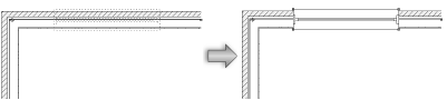
 Inserting windows
|
Mode |
Tool |
Tool set |
Shortcut |
|
Modes for The Symbol Insertion tool |
Window
|
Building Shell |
Shift+D (Windows) Option+Shift+W (Mac) |
To insert a window:
Click the tool and appropriate modes.
Alternatively, if placing a curtain wall window into a curtain wall, select a panel with the Edit Curtain Wall tool, and then right-click on the panel and select Insert Window from the context menu. The window is automatically inserted as a curtain wall window.
Do one of the following:
Click Window Style on the Tool bar to select a resource from the Resource Selector.
Individual manufacturer catalog items cannot be selected using the Resource Selector; see Concept: Plug-in object styles and catalog items.
Click Preferences to open the Window Preferences dialog box and specify the tool’s default parameters.
The parameters can be edited later from the Object Info palette. Additional parameters are available from the Object Info palette itself, as described in Window properties.
Click in the drawing area or in a wall (standard wall or curtain wall) to set the insertion point of the window, and click again to set the rotation. When inserting a window into a wall, place the second click on the exterior side of the wall to establish the exterior direction of the window. To change the direction of a window inserted in a wall, click Flip from the Object Info palette.
Several features of the window are described as “interior” or “exterior.” These include trim, shutters, and wall-wrap parts. These elements are determined based on the internal and external faces of the wall, not on the window’s exterior direction. The left side of the wall (as viewed along the wall direction) is always “exterior,” and the right side is “interior” (see Wall direction). Flipping the window does not flip these elements.
If you are inserting a corner window, place the window in a wall that is attached to another wall. Once parameters are set, the window moves to the nearest corner automatically. This represents one half of the corner window assembly.
Optionally, create a style resource from an unstyled object (see Custom plug-in object styles with catalog options).
Window settings
You can create plug-in objects with a combination of parameters that are determined by the manufacturer’s catalog item, by style and/or by instance, and then optionally save them as a plug-in object style. Catalog parameters have a fixed value established by the manufacturer and cannot be edited by the user. Style parameters have a fixed value established by the style; instance parameters can be set independently for each instance of the object in the drawing (see Concept: Plug-in object styles).
Additional plug-in object settings for the class, the 2D component and cut plane display, and wall insertion are available; see Additional plug-in object style and instance options.
Click to show/hide the parameters.Click to show/hide the parameters.
|
Parameter |
Description |
|
Use Style |
To create a custom window, leave the Unstyled setting. To use an existing window from the resource libraries, click Use Style; from the Resource Selector, double-click a resource to activate it. |
|
Convert to Unstyled |
If Use Style is currently set to a style, select this option to convert the object to unstyled; the current values are retained, but all parameters on all panes are set to By Instance to allow editing |
|
By Catalog/Style/Instance |
A graphic indicates whether each parameter within the style is set to By Catalog and defined by the catalog item, set to By Style and given a fixed value by the user, or set to By Instance and editable in the dialog box. An object style may have a combination of all three of these settings, to balance the need for consistency and flexibility. By Catalog/Style/Instance settings are established by the style and cannot be changed from the settings dialog box.
To edit the object style, see Editing plug-in object styles; editing the style modifies all plug-in objects in the file that use the style. |
|
Select from Catalog
|
If the catalog item is set by instance, opens the Catalog dialog box for Selecting catalog items for plug-in object styles. If a current catalog item is associated with the style, static text displays the item’s description. The catalog item itself can be set to By Style (to ensure that all objects using that style use the same catalog item) or to By Instance (if, for example, different sizes of the otherwise identical object require different catalog items). |
|
3D Preview |
Dynamically displays a 3D preview of the window with the currently selected parameters |
|
View |
Select the standard view for the 3D preview of the window |
|
Render |
Select the render mode for the 3D preview of the window |
|
Detail |
Select the detail level for the 3D preview of the window |
|
Top/Plan Preview |
Dynamically displays a Top/Plan preview of the window with the currently selected parameters |
|
Detail |
Select the detail level for the Top/Plan preview of the window |
Window settings: General pane
Click to show/hide the parameters.Click to show/hide the parameters.
|
Parameter |
Description |
|
Window Shape |
Select the window shape. All window shapes other than rectangular are fixed glass; only the appropriate parameters on each pane of the Window Settings dialog box are available for these fixed glass shapes. |
|
Top Shape |
Select the shape of the top of the window |
|
Include transom |
Adds a transom above the window; transom parameters are set from the Transom pane |
|
Rise |
When applicable for the selected Top Shape, enter the distance between the start of the top shape to the top of the window |
|
Spring |
Enter the distance traveled above the bottom pane before the top shape starts; if Square is selected as the Top Shape, the spring is the total height |
|
Sash |
Select the window type. Depending on the selection, a variety of window settings are enabled or disabled automatically, as described in the following sections. To create a simple opening in a wall for defining a window break without creating any geometry to represent the window, select the Opening option. To define a custom window sash, select Custom Sash and click Custom Sash Options to open the Custom Sash Options dialog box (See Creating a custom window sash opening). |
|
Operation |
A variety of options are available; X represents an operational slider and O represents a fixed sash. For Horizontal Slider Sash windows, choose the desired operation for creating a two-, three-, or four-panel sash. Picture Window Slider Sash windows from files imported from older versions of Vectorworks will have the XX Operation applied. Picture Window Slider Sash windows created will have the XOX Operation applied and will have Unequal sash selected in the Jamb and Sash pane and the Custom Sash Options dialog box. |
|
Select Use symbol geometry and click Browse to select a window symbol. Click the Symbols selector. From the Resource Selector, double-click a different symbol to apply it. The symbol Name displays in the Window Settings dialog box and the preview is updated with the selected symbol. When a symbol is selected, all fields pertaining to the window’s geometry are overridden by the symbol geometry; however, parametric values are still available for scheduling and reporting purposes only. |
|
|
Size Reference |
Select the appropriate option to define the window width and height; the Size Reference selection automatically updates the Width and Height fields, but does not change the size of the window: Sash Opening: this represents the window opening including the sash and glass, but excluding the transom and jamb; this is typically used to show the window opening for emergency exit purposes. Unit Size: this represents the current overall window width and height, including the transom and sash; this is the default setting for imperial units. Rough Opening: this represents the current overall window width and height, including the transom, sash, and shim gap (for the Opening Sash configuration, the Size Reference is automatically changed to Rough Opening); this is the default setting for metric units. |
|
Width/Height |
The width/height of the window is measured based on the Size Reference selection: Sash Opening: width/height is measured at the outside of the sash. Unit Size: width/height is measured at the outside of the jamb. Rough Opening: width/height measures the rough opening. For circle, half circle, hexagon, and octagon shaped windows, the height parameter is disabled, and the parameter is automatically calculated based on the window’s width. |
|
Elevation in Wall |
Enter the window elevation |
|
Elevation Reference |
Select either the sill or the head of the window as the elevation reference point |
|
Insertion Relative to |
Specify whether the insertion point is relative to the exterior face, center, or interior of the jamb. Additional wall insertion options are available, as described in Additional plug-in object style and instance options. |
|
Curtain wall window |
Indicates that the window will be placed in a curtain wall, where its width and height are based on the surrounding panel size and the bottom frame where it is placed. A curtain wall window does not have as many available parameter options as a standard window. Configurations are limited to those that apply to curtain wall placement. |
|
Create niche for space objects |
Creates niche geometry that space objects can include in their net boundary areas; see Space settings: 2D Boundaries and Area pane |
Window settings: 2D Visualization pane
Click to show/hide the parameters.Click to show/hide the parameters.
|
Parameter |
Description |
|
Draw wall lines |
Draws wall lines at all times; wall lines are drawn in the Ceiling-Main class to easily create reflected ceiling plans |
|
Set Attributes By |
Select whether to set the 2D graphic attributes and visibility of the listed window parts by Object, Line Style, or Class. Object: disables line style and weight controls for individual parts, and uses the line style and weight settings for the window object. Line Style: controls line style and weight for the individual parts; these settings override the window object’s settings. Class: sets the line style and weight of individual parts by class. To control appearance and visibility, select a class from the list of classes present in the drawing, or create a new class. Select <Window Class> to place the part attributes in the same class as the window object. |
|
Visibility Classes |
To control appearance and visibility, select a class for each part from the list of classes present in the drawing, or create a new class. Select <Window Class> to place the part attributes in the same class as the window object. |
Window settings: 3D Visualization pane
3D Visualization options are not enabled for the Opening Sash configuration.
Click to show/hide the parameters.Click to show/hide the parameters.
|
Parameter |
Description |
|
3D Hinge Direction Marker |
|
|
Show interior/exterior marker |
Draws lines representing the hinge direction of the window sashes on the interior/exterior side of the window in 3D |
|
Use hinge marker class attributes |
Sets the hinge direction marker’s attributes by class |
|
Hinge Direction Marker Class |
To control visibility and, if Use hinge marker class attributes is selected, appearance, select a class from the list of classes present in the drawing, or create a new class. Select <Window Class> to place the hinge marker in the same class as the window object. |
|
Marker Points Towards |
Set the hinge direction marker to point toward the hinge or toward the handle |
|
Show 3D open |
Draws 3D window sashes as open at the specified Open Angle |
|
Clerestory |
Draws the window as dashed in Top/Plan views if the sill is higher than the specified elevation and draws the window as non-breaking (solid) if the sill is below the specified Cut-plane Elevation. For correct clerestory display in horizontal section viewports, whether above, below, or cut by the viewport’s cut plane, the window object automatically creates 2D components for the Top and Top and Bottom Cut views (see Creating 2D components for symbol definitions and plug-in objects). If the Top/Plan Clerestory setting is set By Style, the instance will override it for horizontal section viewports. |
|
Cut-plane Elevation |
When the design layer cut plane is enabled (Vectorworks Architect required), the elevation of the window cut plane is set to the same value as that of the design layer, ensuring a uniform cut plane appearance for the layer. When the design layer cut plane is disabled, or for the Vectorworks Spotlight or Landmark products, specify a cut plane elevation for the window when Clerestory is selected. |
|
3D Detail Levels |
Vectorworks automatically produces window representations in low, medium, and high detail levels for display at different scales, but some window parts are left for you to determine. Set the detail levels for the listed window parts to display in a design layer view or viewport. The Muntins list item controls the display for all muntins in the window; Trim controls interior and exterior window trim. Vectorworks can automatically display the desired detail level based on the design layer’s scale; see Document preferences: Display tab. Different levels of detail can also display for different scale viewports. Once the window parts’ detail levels are established, set each viewport to display the desired Detail Level when creating the viewport, or set this from the Object Info palette. |
Window settings: ID Tag pane
Click to show/hide the parameters.Click to show/hide the parameters.
|
Parameter |
Description |
|
Include on schedule |
Includes this window’s information in the window schedule; see Creating window schedules |
|
Show tag in 2D |
Displays the ID tag in Top/Plan view |
|
ID Prefix |
Places a prefix before the label value |
|
ID Label |
Enter a label to identify the window |
|
ID Suffix |
Places a suffix after the label value |
|
ID Class |
To control visibility and, if Use ID class attributes is selected, appearance, select a class from the list of classes present in the drawing, or create a new class. Select <Window Class> to place the ID class attributes in the same class as the window object. |
|
Use ID class attributes |
Uses the ID class attributes for the bubble line, leader line, and leader line marker |
|
Keep ID horizontal |
When selected, automatically rotates the ID so that it is horizontal |
|
Bubble Shape |
Select the ID tag bubble shape |
|
Bubble Size |
Enter the minimum bubble size (this value represents the bubble size times the layer scale; the bubble shape is maintained relative to the text inside it for ID bubble uniformity throughout the drawing file) |
|
Bubble Line Attributes |
Select the bubble line attributes and weight, or select Set Thickness to open the Set Thickness dialog box for creating a custom line thickness |
|
Show leader |
Draws a leader line from the ID tag to the window object |
|
Line Attributes |
Select the leader line attributes and weight, or select Set Thickness to open the Set Thickness dialog box for creating a custom line thickness |
|
Include marker |
Includes a marker for the ID leader line and choose the desired style from the marker list, or select Custom to create a custom marker. Select Edit Marker List to open the Edit Marker List dialog box; see Editing the marker list. |
|
Show tag in 3D |
Displays the ID tag in 3D views |
|
Horizontal Offset |
If Show tag in 3D is selected, enter the horizontal offset of the 3D ID tag relative to the bottom left corner of the rough opening when looking at the exterior side of the window (a positive value moves the tag inside the opening relative to the starting corner; a negative value moves the tag outside the opening relative to the starting corner). The ID tag is offset slightly from the outside face of the window sash. The size and shape of the text and bubble, if present, will match the plan settings, and the text will always be right reading from the outside of the wall. The bubble will scale with text scaling in viewports. |
|
Vertical Offset |
If Show tag in 3D is selected, enter the vertical offset of the 3D ID tag relative to the bottom left corner of the rough opening when looking at the exterior side of the window (a positive value moves the tag inside the opening relative to the starting corner; a negative value moves the tag outside the opening relative to the starting corner) |
Window settings: Corner Window pane
Corner Window options are not enabled for non-rectangular window shapes or for curtain wall windows.
Click to show/hide the parameters.Click to show/hide the parameters.
|
Parameter |
Description |
|
Corner window |
Redraws the current window as a corner window. Settings that do not apply to a corner window may be disabled or changed when the corner window option is selected. When you click OK to exit the Window Settings dialog box, the window is moved to the corner of the wall to which it is most closely located. To complete the corner window, insert another one into the adjacent, attached wall. Corner windows do not work in tandem with one another. When you make adjustments to one window, you also need to update the other. This can be accomplished quickly with the Eyedropper tool or from the Object Info palette. When you make adjustments to the wall containing a corner window, the window moves along with the wall and remains locked in the corner position. When adjusting the angle of the wall, the miter is automatically adjusted in most cases; if a corner window object does not automatically update, temporarily change a parameter from the Object Info palette to force a reset of the window object. |
|
Span wall |
Automatically adjusts the width of the window to match the span of the wall, and miters the window edges to the wall corners; therefore, the Width parameter in the General pane and Object Info palette is grayed |
|
Corner Condition |
Select the type of corner window: Opening: creates a simple opening in a wall for defining a window break without creating any geometry to represent the window (the Sash configuration also changes automatically to Opening). Cased Opening: creates a simple opening in a wall with geometry outlining the window break. Sash is set to Cased Opening. Flush Glass/Flush Glass - No Sash: draws the glass right to the edge of the wall and wraps it around the corner, with a Sash set to Flush Glass or without a sash. Mitered Sash: draws the window with a mitered sash in the corner. Corner Post: draws the window with a post in the corner; specify the Size of the post, its Offset within the wall, and the type of Sash for the window. |
|
Sash |
Select the window type. Depending on the selection, a variety of window settings are enabled or disabled automatically, as described in the following sections. To create a simple opening in a wall for defining a window break without creating any geometry to represent the window, select the Opening option. To define a custom window sash, select Custom Sash and click Custom Sash Options to open the Custom Sash Options dialog box (See Creating a custom window sash opening). |
|
Operation |
A variety of options are available; X represents an operational slider and O represents a fixed sash. For Horizontal Slider Sash windows, choose the desired operation for creating a two-, three-, or four-panel sash. Picture Window Slider Sash windows from files imported from older versions of Vectorworks will have the XX Operation applied. Picture Window Slider Sash windows created will have the XOX Operation applied and will have Unequal Sash selected in the Jamb and Sash pane and the Custom Sash Options dialog. |
Window settings: Jamb and Sash pane
Jamb and Sash options are not enabled for the Opening Sash configuration.
Click to show/hide the parameters.Click to show/hide the parameters.
|
Parameter |
Description |
|
Jamb |
|
|
Jamb Width |
Enter the face width of the window jamb (parallel to the wall) |
|
Jamb Depth |
Enter the depth of the window jamb (perpendicular to the wall) |
|
Use wall depth |
Sets the jamb depth to the overall wall depth |
|
Use jamb extension |
Select this field to specify a jamb extension to fill any gap between the interior face of the jamb and the interior face of the wall; enter the desired Jamb Extension Width. In 2D views, extensions use the Jamb line styles and weights; in 3D views, the extension fill color and/or textures and visibility are controlled by the Interior Jamb class. |
|
Sash |
|
|
Sash Width |
Enter the sash width |
|
Sash Depth |
Enter the sash depth |
|
Sash Offset |
Enter the offset of the sash relative to the jamb depth (a positive value moves the sash toward the window exterior; a negative value moves the sash toward the window interior) |
|
Sash Width Offset |
Enter the sash width offset relative to the jamb width (leaving the default value of 0 keeps the sash adjacent to the jamb, and a positive value makes the sash intersect the jamb; a negative value is not permitted) |
|
Glass Offset |
Enter the glass offset relative to the sash depth (a positive value moves the glass toward the window exterior; a negative value moves the glass toward the window interior) |
|
Unequal sash |
Creates a double hung window with an unequal sash height; enter the desired scale factor for the top sash. Picture Window Slider Sash windows will automatically have Unequal sash selected to differentiate it from a horizontal slider sash with an XOX operation. Enter the desired scale factor for the sashes. The sash scale factor applies to both the left and right sliders. |
|
Shim Gap |
Enter the distance between the jamb exterior face and the rough opening (for the Opening Sash configuration, the Shim Gap is automatically set to 0) |
|
Show shim gap in plan |
Displays the shim gap in Top/Plan view |
|
Masonry Module |
Enter the masonry module dimension |
|
Glazing Thickness |
Enter the glazing thickness for the sash |
Window settings: Sill pane
Sill options are not enabled for the Opening Sash configuration or for non-rectangular window shapes, or for curtain wall windows.
Click to show/hide the parameters.Click to show/hide the parameters.
|
Parameter |
Description |
|
Include sill |
Includes a sill |
|
Sill Type |
Select the sill type and specify the measurements |
Window settings: Louvers pane
Louver options are not enabled for the Cased Opening and Opening Sash configurations. Fixed Glass is the recommended Sash configuration. To use louvers in a corner window, select Mitered Sash or Corner Post for the Corner Condition.
Click to show/hide the parameters.Click to show/hide the parameters.
|
Parameter |
Description |
|
Replace glazing with louvers for |
Replaces the glazing in the Transom and/or Sash with louver vents |
|
Louver Type |
Select the louver style and specify the measurements |
|
(1) Blade Spacing |
Enter the center to center distance between the blades |
|
(2) Blade Angle |
Enter the angle of the louver blades |
|
(3) Blade Lip/Thickness |
Enter the height of the visible lip/thickness of the blades |
|
(4) Louver Depth |
Enter the depth of the louvers, typically the same as the Sash Depth on the Jamb and Sash pane |
Window settings: Transom pane
Transom options are not enabled for the Opening Sash configuration or for non-rectangular window shapes, or for curtain wall windows.
Click to show/hide the parameters.Click to show/hide the parameters.
|
Parameter |
Description |
|
Sash |
|
|
Sash Width/Depth |
Enter the transom sash width/depth |
|
Sash Offset |
Offsets the sash from the center of the jamb. A positive value moves the sash toward the exterior of the window, and a negative value moves the sash toward the interior of the window. |
|
Mullion |
|
|
Mullion Width/Depth |
Enter the transom mullion width/depth |
|
Use Jamb Depth |
Overrides the transom Mullion Depth with the jamb depth. When this field is selected, Mullion Depth is grayed. |
|
Muntins |
|
|
Include muntins |
Adds muntins to the transom |
|
Pattern |
Select the transom muntin pattern |
|
Vertical/Horizontal Bars |
For colonial muntins, enter the number of vertical/horizontal muntin bars. Prairie and renaissance muntins come with pre-set configurations; therefore, any number of Vertical/Horizontal Bars specified are disregarded. |
|
Bar Width/Depth |
Enter the transom muntin bar width/depth |
|
Bar Offset |
Enter the transom muntin bar offset |
|
Number of Rays |
For sunburst patterns, enter the number of muntin rays |
|
Glazing Thickness |
Enter the glazing thickness for the transom |
Window settings: Trim pane
Trim options are not enabled for the Opening Sash configuration or for curtain wall windows.
Click to show/hide the parameters.Click to show/hide the parameters.
|
Parameter |
Description |
|
Include interior/exterior trim |
Includes interior/exterior trim |
|
Width/Depth |
Enter the interior/exterior trim width and depth |
|
Include trim under stool/sill |
Includes interior/exterior trim along the window bottom |
Window settings: Lintel pane
Lintel options are not enabled for the Opening Sash configuration or for non-rectangular window shapes, or for curtain wall windows.
Click to show/hide the parameters.Click to show/hide the parameters.
|
Parameter |
Description |
|
Include lintel |
Adds a lintel above the window or transom |
|
Interior/Exterior Protrusion |
Enter the interior and exterior lintel protrusion |
|
(1) Thickness |
Enter the lintel thickness |
|
(2) Angle |
Enter the lintel angle |
|
(3) Drop |
Enter the length of the lintel drop |
Window settings: Muntins pane
Muntin options are not enabled for the Opening Sash configuration or for non-rectangular window shapes.
Click to show/hide the parameters.Click to show/hide the parameters.
|
Parameter |
Description |
|
Top sash/Bottom sash |
Adds top and/or bottom sashes to the muntins |
|
Pattern |
Select the muntin pattern |
|
Vertical/Horizontal Bars |
For colonial muntins, enter the number of vertical/horizontal muntin bars. Prairie and renaissance muntins come with pre-set configurations; therefore, any number of Vertical/Horizontal Bars specified are disregarded. |
|
Bar Width/Depth |
Enter the muntin bar width/depth |
|
Bar Offset |
Enter the muntin bar offset |
|
Number of Rays |
For sunburst patterns, enter the number of muntin rays |
|
Custom top sash muntins |
For a double hung window with an unequal sash and colonial muntins, customizes the top sash; enter the desired number of Horizontal Bars |
Window settings: Interior Shutters pane
Interior Shutter options are not enabled for the Opening Sash configuration or for non-rectangular window shapes, or for curtain wall windows.
Click to show/hide the parameters.Click to show/hide the parameters.
|
Parameter |
Description |
|
Include interior shutters |
Includes interior shutters |
|
Use custom width |
If Square is selected as the window’s Top Shape, creates interior shutters of a width other than the default value (1/2 the width of the window); enter the custom width |
|
Frame Depth |
Enter the depth for the interior shutters |
|
Offset from Jamb |
Enter the offset distance from the interior edge of the window jamb that shutters will be positioned when fully opened |
|
Panel shutter |
Creates paneled shutters |
|
Panel Frame Width |
Enter the rail and stile width of the paneled shutter |
|
Number of Panels |
Select One panel per sash to divide shutters at sash divisions or select to divide panels equally by the Custom number of panels specified |
|
Custom shutter |
Click Choose Symbol to select a custom shutter symbol from default content; see Concept: Resource libraries. Custom shutters must be 3D-only symbols made from generic solids, saved in the default content location. |
Window settings: Exterior Shutters pane
Exterior Shutter options are not enabled for the Opening Sash configuration or for non-rectangular window shapes, or for curtain wall windows.
Click to show/hide the parameters.Click to show/hide the parameters.
|
Parameter |
Description |
|
Include exterior shutters |
Includes exterior shutters |
|
Use custom width |
If Square is selected as the window’s Top Shape, creates exterior shutters of a width other than the default value (1/2 the width of the window); enter the custom width |
|
Frame Depth |
Enter the depth for the exterior shutters |
|
Offset from Jamb |
Enter the offset distance from the interior edge of the window jamb that shutters will be positioned when fully opened |
|
Panel shutter |
Creates paneled shutters |
|
Panel Frame Width |
Enter the rail and stile width of the paneled shutter |
|
Number of Panels |
Select One panel per sash to divide shutters at sash divisions or select to divide panels equally by the Custom number of panels specified |
|
Custom shutter |
Click Choose Symbol to select a custom shutter symbol from default content; see Concept: Resource libraries. Custom shutters must be 3D-only symbols made from generic solids, saved in the default content location. |
Window settings: Centerline Marker pane
Centerline Marker options are not enabled for curtain wall windows.
Click to show/hide the parameters.Click to show/hide the parameters.
|
Parameter |
Description |
|
Centerline marker |
Displays a centerline marker in Top/Plan view |
|
Size |
Set the size of the centerline |
|
Class |
To control visibility, select a class from the list of classes present in the drawing, or create a new class. Select <Window Class> to place the centerline marker attributes in the same class as the window object. |
|
Line Attributes |
Select the line attributes and weight, or select Set Thickness to open the Set Thickness dialog box for creating a custom line thickness. If Use class attributes is selected, the line attributes are set by the part’s class. |
|
Include marker |
Includes a marker at the end of the line; choose the desired style from the marker list, or select Custom to create a custom marker. Select Edit Marker List to open the Edit Marker List dialog box; see Editing the marker list. If Use class attributes is selected, the marker attributes are set by the part’s class. |
|
Use class attributes |
Sets the centerline marker’s attributes (including marker style) by class rather than the parameters in the Window Settings dialog box |
Window settings: Interior Wall Detail pane
Interior Wall Detail options are not enabled for non-rectangular window shapes or for curtain wall windows. For more extensive component wrapping and wall profile options, see Wall closure settings.
Click to show/hide the parameters.Click to show/hide the parameters.
|
Parameter |
Description |
|
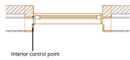
Number of Components |
Specify the number of interior wall components to wrap; when interior wall components are specified, the window enables a control point to set the wrapping point
|
|
Splay wall |
Splays the interior wall; the splay can be specified either as an angle/diagonal or with width and depth values |
|
(1) Splay Angle |
Enter the interior wall splay angle |
|
(2) Splay Diagonal |
Enter the interior wall splay diagonal value |
|
(3) Splay Width |
Enter the interior wall splay width |
|
(4) Splay Depth |
Enter the interior wall splay depth |
Window settings: Exterior Wall Detail pane
Exterior Wall Detail options are not enabled for non-rectangular window shapes or for curtain wall windows. For more extensive component wrapping and wall profile options, see Wall closure settings.
Click to show/hide the parameters.Click to show/hide the parameters.
|
Parameter |
Description |
|
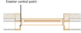
Number of Components |
Specify the number of exterior wall components to wrap; when exterior wall components are specified, the window enables a control point to set the wrapping point
|
|
Splay wall |
Splays the exterior wall; the splay can be specified either as an angle/diagonal or with width and depth values |
|
(1) Splay Angle |
Enter the exterior wall splay angle |
|
(2) Splay Diagonal |
Enter the exterior wall splay diagonal value |
|
(3) Splay Width |
Enter the exterior wall splay width |
|
(4) Splay Depth |
Enter the exterior wall splay depth |
Window settings: Classes pane
The visibility of the overall 3D window is controlled by the Class setting from the Object Info palette; part settings are controlled from the Window Settings dialog box.
Click to show/hide the parameters.Click to show/hide the parameters.
|
Parameter |
Description |
|
Window parts |
To control appearance and visibility, select a class from the list of classes present in the drawing, or create a new class. Select <Window Class> to place the part attributes in the same class as the window object. For windows with an Opening Sash configuration, in a 3D view, a no fill/no pen weight extrude completely fills the wall in place of the window; this extrude is placed in the Interior Jamb class and is filtered out in IFC export operations. Change the class settings to control the visibility of the extrude. |
 Window settings: Energos pane
Windows play a critical role in energy analysis calculations. Energy is lost through the window glass, but energy is also gained by solar radiation through the window glass. Accurately determining the R-Value/U-Value and the shading factor is essential for the overall energy analysis.
Vectorworks Architect is required to conduct an energy analysis; however, energy-related parameters can be specified here for informational purposes.
Click to show/hide the parameters.Click to show/hide the parameters.
|
Parameter |
Description |
|
Include in calculations |
When selected, the window is eligible to be included in energy calculations, depending on the energy analysis settings for layer/class, element inclusion, and so on |
|
R-Value/U-Value |
|
|
Automatic Calculation |
Based on the frame and glazing parameters, the window R-Value/U-Value is calculated and displayed. This value, along with the window shading factors, is critical for a correct assessment of the building envelope in energy calculations. |
|
Manual Input |
Select this option to override the calculated R-Value/U-Value and enter a manual value for the window instead. For complex or detailed window designs, enter results from a third-party calculation here. |
|
Frame |
Select the thermal properties of the frame. Sets can be created and edited; see Specifying system sets. |
|
Glazing |
Select the thermal properties of the window glazing. Sets can be created and edited; see Specifying system sets. |
|
Shading |
Select the level of shade for each type of shading near the window, or select Custom from any of the lists. The Edit Shading dialog box opens, to manually enter a percentage for when the window is in the shade. |
|
General |
Select the general shade conditions where the window is located |
|
Surrounding |
Specify surrounding shade conditions that might affect the amount of solar radiation reaching the window |
|
Summer Shading |
Specify special shade conditions that apply during the summer months (for example, when nearby deciduous trees shade the window) |
|
Additional Shading |
Select any mechanical or passive shading mechanisms in place, or select Custom and enter a shading percentage in the Edit Shading dialog box |
|
Summer Ventilation |
Opens the Summer Ventilation Settings dialog box, to specify summer ventilation options for when the window is typically open. If the window participates in summer ventilation, in the Energos Project Settings dialog box, select Include Summer Ventilation on the Systems-Ventilation tab, and click Advanced to set the global summer ventilation settings for windows on the ground and upper floors, and at night. See Energos advanced project settings: Systems Ventilation pane. Advanced summer ventilation options (ground floor, upper floor, night): Select the type of ventilation system usage, if any, for the window. Operable opening width: Indicates the width of the window opening gap for an operable window (which affects the amount of ventilation). |
Window settings: Data pane
Certain data fields represent calculated values and cannot be edited; as a result, the Field Name and Field Value are grayed for those data fields.
Click to show/hide the parameters.Click to show/hide the parameters.
|
Parameter |
Description |
|
Field Name |
Select the data field from the list and its name displays beneath the list; information associated with the Field Name can be specified in the Field Value area. The user fields can include additional user-defined information with the window. |
|
Field Value |
Enter data for use in the window schedule |
