 Elevation benchmark settings
These settings are available in the following locations:
Elevation Benchmark Preferences dialog box, when creating a new elevation benchmark object
Elevation Benchmark Style dialog box, when editing an elevation benchmark style
Elevation Benchmark Settings dialog box, when editing an elevation benchmark object
Object Info palette, when editing an elevation benchmark object
If a style is selected, only parameters set by instance can be edited (see Concept: Plug-in object styles).
Click to show/hide parametersClick to show/hide parameters.
|
Parameter |
Description |
|
Use Style |
Opens the Resource Selector to select a resource for placement |
|
Convert to Unstyled |
If Use Style is currently set to a style, select this option to convert the object to unstyled; the current values are retained, but all parameters are set to By Instance to allow editing |
|
Axis of Measure |
Specifies whether the Y-axis (in 2D mode) or Z-axis (in 3D mode) is used for the elevation value |
|
Benchmark Datum |
Opens a list of options for calculating the marker's elevation value. The options available depend on whether the Axis of Measure is set to the Y or Z axis. Control Point: (Y-axis only) Allows the elevation value to be referenced from a control point displayed on the drawing, rather than from the active layer plane. If the control point is moved, the elevation value remains set by the distance from the control point to the elevation benchmark object. This allows you to set a control point at the ground floor of a house, for example, so that the elevation benchmark value is set according to the height from the ground floor. User Reference (Z-axis): The elevation is the Z value of the elevation benchmark object, plus the elevation of the object's layer, minus the Reference Elevation value User Reference (Y-axis): The elevation is the Y value of the elevation benchmark object, minus the Reference Elevation value Custom: The elevation is the Custom Elevation value Ground Plane: (Z-axis only) The elevation is the Z value of the elevation benchmark object, plus the elevation of the object’s layer Design Layer Z: (Z-axis only) The elevation is the Z value of the elevation benchmark object <Story> or story level: (Z-axis only, Architect or Landmark required) The elevation is the selected story or story level elevation value; if desired, enter an Offset value |
|
Reference Elevation |
If Benchmark Datum is set to User Reference, specifies the reference elevation value |
|
Custom Elevation |
If Benchmark Datum is set to Custom, specifies the marker's elevation value |
|
Offset (Architect or Landmark required) |
If Benchmark Datum is set to a story or story level, specifies an offset from the story or story level's elevation value |
|
Note |
If the marker layout includes a note, enter it here |
|
Elevation Prefix |
If the marker layout includes a prefix (such as +), enter it here |
|
Elevation Suffix |
If the marker layout includes a suffix (such as AMSL), enter it here |
|
Primary Units |
Specifies the units to use for the elevation value |
|
Rounding Precision |
Specifies the precision to use when rounding the elevation value |
|
Show unit mark |
Displays a unit mark along with the elevation value |
|
Marker Scale Factor |
Adjusts the elevation benchmark size |
|
Use horizontal leader |
Adds a leader line to the elevation benchmark |
|
Leader Line Style |
If Use horizontal leader is selected, specifies a style for the leader line |
|
Leader Pen Color |
If Use horizontal leader is selected, specifies a color for the leader line |
|
Apply pen foreground to all graphics |
Select to apply the pen foreground color set in the Attributes palette to the marker graphics; this overrides the Leader Pen Color |
|
Edit Marker Layout |
Opens an editing window to define the geometry of the elevation benchmark and the text fields shown on it; see Editing the elevation benchmark layout. The preferences dialog box indicates whether this setting is by style or by instance, but it cannot be edited. |
|
Object Info palette only |
|
|
Style |
Replace, edit, or remove the current style, or (for unstyled objects only) create a new plug-in style (see Custom plug-in object styles without catalog options). Editing a style changes all instances in the file that use the style. |
|
Hide style parameters |
Hides the parameters that are set by style; these cannot be edited from the Object Info palette |
|
Settings |
Opens the Elevation Benchmark Settings dialog box |
|
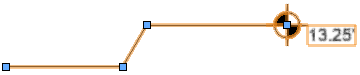
Use leader offset |
If Use horizontal leader is selected, offsets part of the leader line and the elevation value to improve readability; drag the handles to adjust the offset if needed
|
Editing the elevation benchmark layout
Edit the layout to adjust the text fields and 2D geometry in the elevation benchmark.
Select the elevation benchmark, and click Edit Marker Layout from the Object Info palette to enter object editing mode (see Object editing mode). For a styled marker, see Editing plug-in object styles. The marker layout editing window opens.
Alternatively, right-click the elevation benchmark and select Edit Marker Layout.
Use the Text tool to add static and/or dynamic text objects to the layout. From the Object Info palette, specify the appearance of the text; see Formatting text.
Static text simply shows the text on each object.
Dynamic text shows information from the drawing (for example, the story level) on each object, in place of the text object. To create dynamic text, select the text object and select Use dynamic text from the Object Info palette. Then click Define Elevation Benchmark Field to open the dialog box and define the field.
Click to show/hide the parameters.Click to show/hide the parameters.
|
Parameter |
Description |
|
Field Label |
Enter the text to display for this field in the marker layout |
|
Field Definition |
|
|
Current Field Definition |
Variables are placed in this field when you specify a data source and click Add to Definition. The definition can include multiple data sources, static text or punctuation, and simple arithmetic operators. This field definition works the same way as the definition in the Define Tag Field dialog box for data tags; see Creating data tag styles. |
|
Data Source |
Specify the source of the data to display on the marker. Different options are available depending on the source. Object Parameters: Select the Parameter Name to use (for example, Elevation). Object Function: Select an object-specific Object Function to use (for example, Story). If you select a numeric data source (for example, the Elevation object parameter), additional fields display for setting the Units and/or Precision to show on the marker. Select Show unit mark to show a unit mark along with the unit value. |
|
Add to Definition |
After you select the details for a data source, this button adds to the variables in the Current Field Definition window |
Edit or add 2D geometry such as arcs, circles, and lines to the layout, if desired.
Use the layout constraints on the Object Info palette to control the positions of the text and 2D objects on the marker. The options available depend on the type of object.
Click to show/hide the constraints.Click to show/hide the constraints.
|
Constraint |
Description |
|
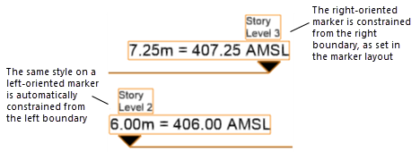
Constrain object distance from boundary |
Constrains the distance of the selected object from the specified boundary (left, right, or both), for a marker oriented to the right side of a drawing object. If you draw the marker oriented to the left side of a drawing object (reversed) the constraint is also automatically reversed.
|
|
Fix width |
For 2D graphic objects, deselect this option to scale the object horizontally to fit the bounding box when necessary |
Exit object editing mode to update the object and return to normal drawing mode.
