 Building a device
|
Tool |
Tool set |
|
Device Builder
|
Schematics |

The device builder allows you to select and place a standard manufacturer device, or create and then place your own device.
If you know the make and model number of a manufacturer’s device, the device builder automatically adds the appropriate sockets and other information.
If you do not know the make or model number, or if you want to modify a standard device, the device builder is still a convenient way of creating a custom device with sockets. The custom device can be created from scratch, or based off of an existing device.
If you only create custom devices, disable the Enable database option in the device builder preferences so that you do not need to scroll through existing make and model information.
A custom device created with the device builder is automatically saved to the device database, and also as a symbol definition available from the Resource Manager.
The Device Builder tool can use the information from the database to place a device with the custom data.
The symbol definition can be placed on the drawing with the Insert Device mode of the Device tool or by double-clicking on the symbol definition from the Resource Manager.
If you click Create Temporary Device, the device is available in the current file as a symbol definition, but it is not saved to the database.
If you have placed a device on the drawing and then made changes to it from the Object Info palette, click Save as Symbol from the Object Info palette to save the edited device as a new symbol definition resource. This saves it as a symbol definition resource, but does not save the edited device data to the database.
To delete a custom device, select it from the Make/Model list in the device builder, and then click Delete (trash can). This prevents temporary or unused devices from cluttering up the Make/Model list.
To insert a device with the device builder:
Click the tool.
Click Preferences on the Tool bar to set the default settings.
The Device Builder Preferences dialog box opens.
Click to show/hide the parameters.Click to show/hide the parameters.
|
Parameter |
Description |
|
Device Appearance |
|
|
Mininum Width (Grid Spaces) |
Sets the minimum width of the device in grid units |
|
Space at Top of Device (Grid Spaces)/Space at Bottom of Device (Grid Spaces) |
Adds space at the top and/or bottom of the device; set the space in grid units. This can help space out devices in a complex drawing and keeps the drawing neat. |
|
Socket Group Spacing (Grid Spaces) |
Sets the space between sockets in grid units |
|
Device Database |
|
|
Enable database |
Allows you to select from the database of existing makes and models when building the device. If you only build custom devices, deselect this option so that you can specify custom information. |
Click to place the device.
The Device Builder dialog box opens. Enter information about the device and its sockets.
Click to show/hide the parameters.Click to show/hide the parameters.
|
Parameter |
Description |
|
Device Browser |
|
|
Category |
Select the category of device, and click the disclosure arrow to select a device type. Enter text in the search box to filter the list. This selection filters the Make/Model list. Alternatively, select <All> to view all makes and models. |
|
Make/Model |
Select the manufacturer, and click the disclosure arrow to select the model name from the list. The available items shown in the list depend on the selection in Category. Enter text in the search box to filter the list. If the model, or even the manufacturer, is not available, you can customize the device. To create a custom make and model, select New Make/Model to open the New Make/Model dialog box. Either select a manufacturer, or select New Make. Enter the custom make name, and then specify the model name. Select a Category for the device; in some cases, this determines which tool can place the device later. For example, a category of Distribution Amplifier means that the customized device can be placed with the Distribution Amplifier tool. The new make and model appear in the Make/Model list under your user name for future selection. If Enable database was not selected in the preferences, the Make and Model are blank so that you can enter custom information. |
|
Delete (trash can) |
Deletes the custom device that is selected from the Make/Model list, removing it from the user folder |
|
Device Identification |
Enter information that appears in labels on the drawing and in worksheets |
|
Device Name |
Enter the name of the device |
|
Display Tag |
Enter the tag name for labels (normally, this is the Device Name) |
|
Display Description |
Enter a description, such as the manufacturer and model name |
|
Label Symbol |
Select a label symbol definition; advanced users can edit the label from the Resource Manager |
|
Enter device physical details |
|
|
Device Type |
|
|
Physical |
Creates a device that can automatically create a corresponding equipment item in the layout with the Create Equipment command |
|
Virtual |
Creates a virtual device, with physical dimensions of 0 for the height, width, and depth. A virtual device cannot be associated with equipment items. |
|
Height/Width/Depth |
Enter the device height, width, and depth in millimeters |
|
Height (Rack Units) |
Enter the height in rack units |
|
Half-rack width |
Sets the width to half of a standard 19” rack (9.5” or 242 mm) |
|
Modular device |
Indicates that the device is modular and is inserted in a rack frame |
|
Module Width (Frame slots) |
For modular devices, enter the number of frame slots required in a rack frame |
|
Power |
Specify the power requirements (the units are set in the ConnectCAD Settings) |
|
Weight |
Enter unit weight (the units are set in the ConnectCAD Settings) |
|
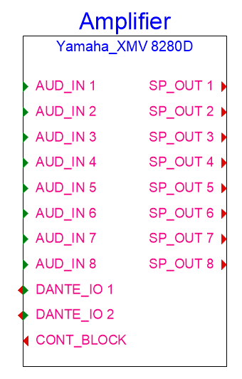
Sockets Definition |
If the manufacturer’s make and model information was recognized by ConnectCAD, the sockets are defined for you. To customize, specify the number of in, out, and IO sockets for each type of signal and connector to be created on the left and right sides of the device. Generally, inputs (and IO) are located on the left, and outputs (and IO) are located on the right. Sockets are added to the device in row order; the rows can be rearranged by clicking and dragging in the # column. Click in the Use column to include or to exclude the socket. For information about the display order of signals and connectors, editing signals, and editing the connectors and cables associated with a signal, see Specifying ConnectCAD settings. |
|
Add/Delete |
Adds sockets to the device, or deletes the currently selected socket row |
|
Duplicate |
Duplicates the currently selected socket row. If desired, you can customize the duplicated row to suit your needs. |
|
Preview |
Displays a preview of the device |
|
Create Temporary Device |
Instead of clicking OK, click this option to create a device that is saved as a symbol, but whose data is not saved in the device database |
Do one of the following:
Click OK to add the device as a symbol definition resource in the current file. The device is also saved in the device database, where it can be used by the device builder (see below).
Click Create Temporary Device to save the symbol as a symbol definition resource only.
Saving a device to the database
You may have a device on the drawing that you've altered or customized to suit your design needs. Save the custom device to the database to be able to easily access it later; the custom device information is saved in your user folder. This is different from using the Save as Symbol option in the Object Info palette, because instead of creating a symbol definition in the file, with this method, you can access your custom device from the Device Builder.
To save a custom device to the database:
Select a device in a drawing.
Jackfields, terminal panels, and connection panels are excluded. For a list of prefixes associated with those devices, see Concept: Specialized device type and prefix.
Click Save to Database from the Object Info palette.
The Device Builder dialog box opens. You can review and, if necessary, edit information about the device and its sockets. (For more information, see Building a device.)
Set the Category of the device, along with any other parameters you want to customize.
The saved custom device is available in the Device Builder dialog box.
