 Placing a basic device or device symbol
The Device tool places a basic device that you can customize, or a device symbol definition. The tool also transfers device properties from one device to another.
|
Mode |
Tool |
Tool set |
|
Basic Device
Insert Device
|
Device
|
Schematics |

![]()
|
Mode |
Description |
|
Basic Device
|
Inserts a generic device with no sockets, ready to customize |
|
Insert Device
|
Inserts device from the Device Symbol list of symbol definitions |
|
Pick up Attributes
|
Copies device characteristics for transfer; see Transferring device properties |
|
Apply Attributes
|
Pastes device characteristics |
|
Single Click (Insert Device mode)
|
Places a single device at the click location |
|
Linear Array (Insert Device mode)
|
Places an array of devices along the drawn line |
|
Device Symbol (Insert Device mode) |
Opens the Resource Selector to select a device resource for placement; double-click a resource to activate it |
|
Eyedropper Transfer Preferences
|
Sets the default transfer items and methods |

To add a device:
Do one of the following:
Click the tool and click Basic Device mode to place a basic, generic device.
Click the tool, click Insert Device mode, and then click Device Symbol on the Tool bar to select a resource from the Resource Selector.
Symbols from the System Symbols folder are not available for placement by the Device tool.
Open the Resource Manager, open the folder containing the devices saved with the file or in the user folder, and then double-click a device. The tool and Insert Device mode are activated, and the Tool bar displays the Device Symbol name.
Place the device. The placement method depends on the selected mode and sub-mode.
In Basic Device mode, click once to set the start point; move the cursor to the opposite corner until the desired size is previewed. Click to insert the device.
In Single Click sub-mode, click once to place the selected symbol instance.
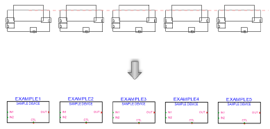
In Linear Array sub-mode, click once to start the array; move the cursor to set the distance and direction of the linear array. Press the Shift key to constrain to the horizontal or vertical direction. The preview indicates the spacing and placement of the objects; the floating Data bar shows the Count. Click to place them.
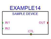
In Insert Device mode with a symbol selected, the device can be placed in the drawing on its own or placed into an existing circuit. To be placed into a circuit, the device needs an input on the left and and output on the right, horizontally opposite.
As the devices are placed, they are automatically numbered. Sequential autonumbering continues for devices with the same name prefix. Select an existing device, and then select the Device tool, to restart the numbering from that device on.
Device parameters
The device parameters can be edited from the Object Info palette. To complete a basic device, the next step is to add sockets as described in Adding sockets, loops, and terminators.
Click to show/hide the parameters.Click to show/hide the parameters.
|
Parameter |
Description |
|
General |
|
|
Device Name |
Enter the name of the device |
|
Symbol |
Displays the symbol selected for the device label; select a different symbol definition from the list if desired. The options include different locations for the tag and description labels. |
|
Display Tag |
Enter the tag name (normally this is the name of the device) for display on the drawing |
|
Description |
Enter a description, such as the manufacturer and model name, for display on the drawing |
|
Manufacturer |
Enter the make and model for use in reports |
|
Save as Symbol |
Saves the device (and its sockets) as a symbol definition that can be accessed for editing from the Resource Manager, and placed on the drawing with Insert Device mode. Enter the name of the new symbol. |
|
Save to Database |
Opens the Device Builder dialog box. You can review and, if necessary, edit information about the device and its sockets. The device is saved to the database, and it is available in the Device Builder dialog box. (For more information, see Saving a device to the database.) |
|
Physical |
|
|
Height/Width/Depth |
Enter the dimensions of the device. Devices with dimensions of 0 are considered virtual devices, which cannot be associated with equipment items. |
|
Power (W) |
Enter the power requirements of the device in watts |
|
Auto BTU calculation |
Automatically converts the power requirements of the device from watts to BTU units (BTU = power in watts x 3.41) |
|
BTU |
To enter power requirements manually, deselect Auto BTU calculation and enter the power requirements of the device in BTU units |
|
Weight (kg) |
Enter the device’s weight in kilograms |
|
Height RU |
Select the height of the device in rack units |
|
Rack Width |
Select whether the width of the device is constrained by the half or the full width of the equipment rack. Select non-rack to use any width, unconstrained by the rack or not placed within a rack. (For more information, see the Rack Width description in Placing equipment.) |
|
Configuration |
|
|
Modular |
Indicates that the device is a module that fits in a rack frame |
|
Number of slots |
For modular devices, enter the number of frame slots required in a rack frame |
|
Location |
If an associated equipment item already exists in the layout, displays the device location; otherwise, if you want to assign the device to a layout, enter the location for the corresponding equipment item |
|
Room |
Enter (or displays) the name of the room |
|
Rack |
Enter (or displays) the name of the equipment rack; the rack name displays on the device |
|
Rack U |
Select (or displays) the position of the device in rack units; the value displays on the device |
|
Edit Device Array |
This functionality is not available for this type of device |
