Pre-cabling the model
|
Tool |
Tool set |
|
Edit Cabling
|
Cable Route |
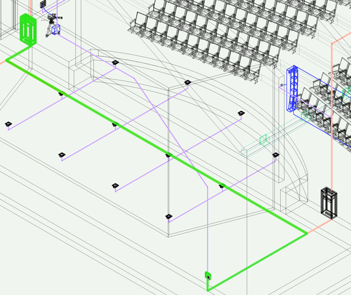
The design of physical cabling may begin long before equipment selection and detailed schematics are finalized. The installers need to know where to install ducts and conduits early in a project, before designers even know exactly what equipment will be placed in the model; you may need to populate cable paths in advance before circuits are assigned to them. Later in the process, you can create the cabling sheet and assign circuits to the cabling for the final schematics.
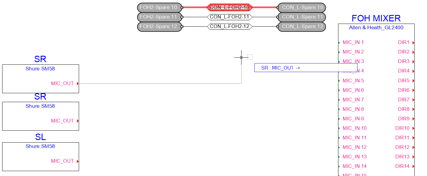
The Edit Cabling tool adds spare cables by one of these methods:
Selecting the starting and ending drop points.
Selecting a cable path that connects two drop points.
If no circuit currently uses the path, there is one route available for the spare cabling (between the drop points).
If circuits use the path, even if it is not directly connected to any drop points but is connected to other paths that connect drop points, spare cabling can be added between the drop points.
You can select an alternative cable path, if available.
The cables are added to a Spare Cabling layer; the layer is created automatically if it does not exist.
The tool is also used to analyze cable path segments, and to select different cable routes for circuits. See Analyzing a cable segment.
To pre-cable the model:
Click the tool.
On the model, do one of the following:
Click on an existing cable path object.
Click on a drop point; if a cable route exists, it is highlighted. Then click on the ending drop point.
If the cable route has not yet been analyzed with the Analyze Cable Routes command, this analysis occurs automatically to verify the existence of a route for each circuit.
The Edit Cabling dialog box opens, displaying the list of circuits that are associated with the cable path segment or that exist between the two selected drop points. Each circuit's parameters display, along with one or more temporary Route Index numbers.
Click to show/hide the parameters.Click to show/hide the parameters.
|
Parameter |
Description |
|
Cable Cross-Section Area |
Estimates the cross-section area from all of the cables in the list |
|
Cable Count |
Displays the total number of cables |
|
Cable List |
Lists the circuits associated with the cable path segment. Cables that are already assigned to circuits are grayed out and cannot be edited; spare cables can be edited. |
|
Circuit parameters |
Displays the parameters of existing and spare circuits; the parameters can be edited. Drop Points displays the names of the source and destination drop points; the Route Index is a temporary number which indicates which rows follow the same cable path segment. |
|
Cable Type/Quantity |
When adding cables, select the kind of cable to add and the number of cables to add |
|
Route Index |
Displays the route indices for the primary route and alternative routes. When there are alternative routes, the Route Index displays several temporary identifiers with a suffix to indicate alternative routes. Suffix A is the shortest, B is the next shortest, and so on. |
|
Add |
Adds a cable with the specified cable parameters to the cable list |
|
Delete |
Deletes the currently selected circuit from the list |
|
Select Alternative Route |
Opens the Select Route dialog box, for selecting a different (potentially longer) route; see Changing cable route assignments |
|
Append to Worksheet |
Opens the Select Worksheet dialog box, to add the list data to an existing worksheet. Alternatively, select New Worksheet to create a new worksheet. |
Create spare cables by selecting the Cable Type, Quantity, and Route Index value, and click Add. The spare cable is added to the Cable List.
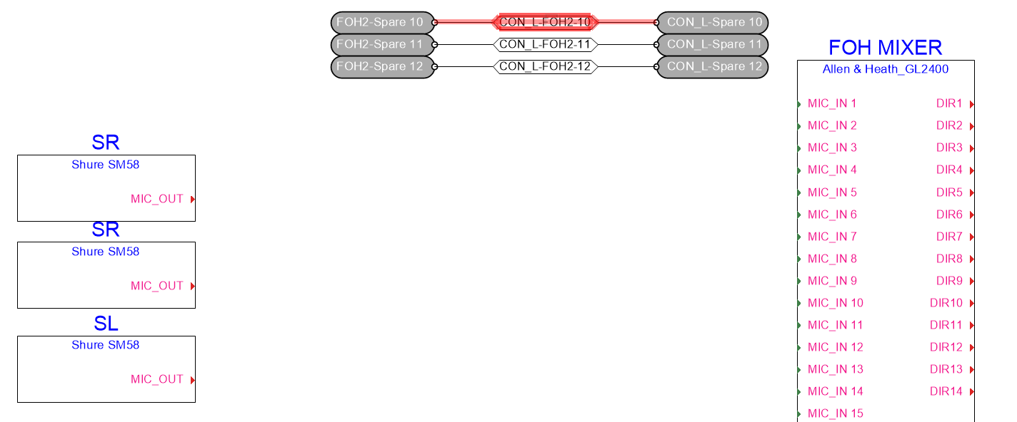
Double-click on a row in the list to highlight the entire route taken by the selected circuit. The drawing pans and zooms temporarily to show the route. Alternative routes through the cable network also display on the drawing, with different colors (change the color, if desired, by clicking on the color box in the circuit list).
Continue adding the necessary spare cables to the list and click OK.
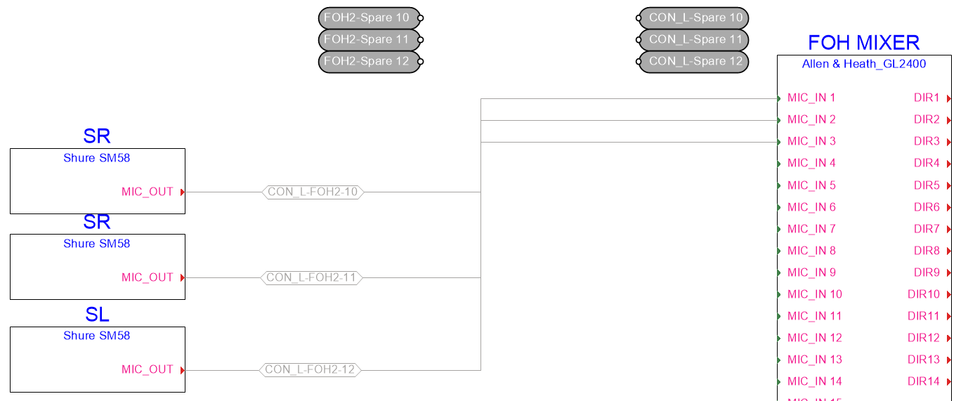
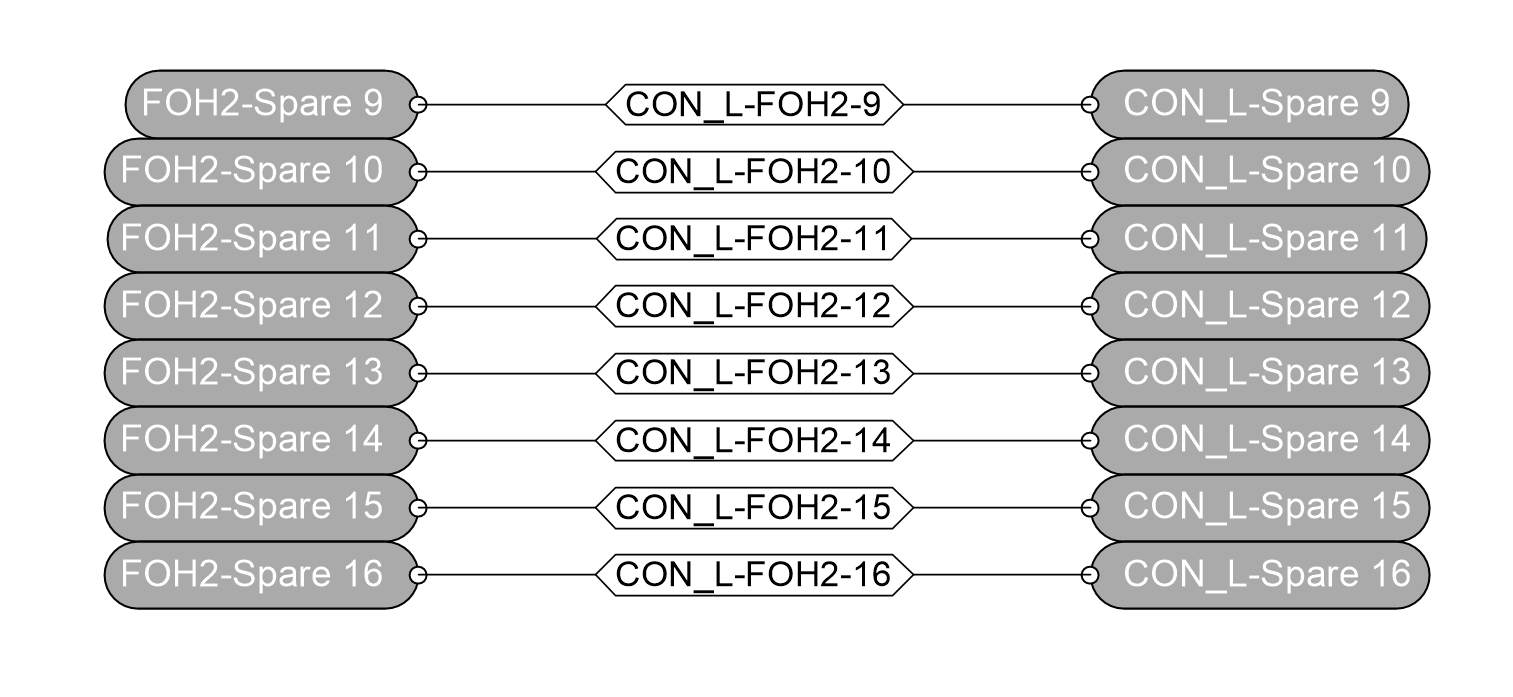
The spare cables in the Cable List are created and placed on the Spare Cabling layer. The cables are temporarily labeled according to the drop points they connect, along with an automatically incrementing number. This makes it easy to locate the spare cables connecting two drop points later.
Assigning spare cables
When it is time to develop the connectivity schematic, use the spare cabling in the actual design, repurposing the circuits from each spare cable with the Redraw Circuit mode of the Connect tool.
|
Mode |
Tool |
Tool set |
|
Redraw Circuit
|
Connect
|
Schematics |


To assign spare cables:
On the final connectivity schematic, create the devices that will be connected by the spare cabling.
Select the spare cables to assign, and move them to the schematic layer by selecting the schematic layer from the Layer list on the Object Info palette.
Select the tool and mode.
Select the spare circuit.
Click on each of the two sockets it connects.
As the circuits are reassigned, they are automatically removed from the spare designation. Delete the spare external labels.