 Analyzing cable paths
The Analyze Cable Routes command and the Edit Cabling tool assist with fine tuning the cable route design, integrating the schematic design with the cable path, and identifying errors that need correction.
Analyzing the cable route
|
Command |
Path |
|
Analyze Cable Routes |
ConnectCAD > Documentation |
This command analyzes the cable path network and assigns each circuit from the schematic to a cable path segment.
This command does not assign circuits to cables placed with the Cable tool. To do this, provide a Run ID in the cable's Object Info palette. On the schematic layer, select the circuit to be assigned, and in the circuit's Object Info palette, select the same Cable from the list to assign the cable to the circuit.
This command excludes cable routes to and from external connections when the devices have <EXT> in the name and they are present in the file.
To analyze the cable routes:
Select the command.
If the analysis is successful, every circuit object in the schematic is associated with a cable path segment. If there are circuits which cannot be associated with the cable path, an error message displays. If the problems are expected—for example, a camera has not yet been attached to the cable path network or to a drop point, or the routing is so obvious that the detailed cable paths weren't necessary—proceed with the design and make the connection later, or not at all. Otherwise, click Mark up Circuits to highlight the circuits which could not be assigned to a cable path, and correct any errors.
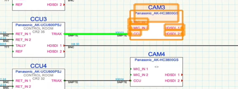
The circuit highlighted in green could not be assigned to a cable segment. Correct the problem by attaching the camera to the cable network with the Cable Route tool.
Analyzing a cable segment
|
Tool |
Tool set |
|
Edit Cabling
|
Cable Route |
This tool displays a list of all the circuits that pass through a particular segment of a cable path.
The tool is also used to create pre-cabling circuits for the Spare Cabling layer. See Pre-cabling the model. It can also select different cable routes for circuits as described in the next section.
To determine the circuits associated with a cable path segment:
Select the tool.
Click on the cable route segment to analyze.
If the cable route has not yet been analyzed with the Analyze Cable Routes command, this analysis occurs automatically to verify the existence of a route for each circuit.
The Edit Cabling dialog box opens, displaying the list of circuits that are associated with the cable path segment. Each distinct circuit's parameters display, along one or more temporary Route Index numbers. Sort the circuits by Route Index to see which circuits share the same path.
In addition to circuits, cables inserted by the Cable tool that are associated with the cable path segment display in the list. The Circuit column entry for these cables is blank.
Double-click on a row in the list to highlight the entire route taken by the selected circuit. The drawing pans and zooms temporarily to show the route. Alternative routes through the cable network also display on the drawing with different colors.
Changing cable route assignments
After analyzing the cable path segments, the Edit Cabling dialog box can be used to assign circuits to a different route. Normally, the shortest route is the most desirable, as selected automatically by ConnectCAD. However, there are exceptions, as in cases where main and backup signals must travel through different routes, or when the physical size of ductwork limits the number of circuits passing through the route.
|
Tool |
Tool set |
|
Edit Cabling
|
Cable Route |
To change the cable route assigment of a circuit:
Select the tool.
Do one of the following:
Click on an existing cable path object.
Click on a drop point; if a cable route exists, it is highlighted. Then click on the ending drop point.
If the cable route has not yet been analyzed with the Analyze Cable Routes command, this analysis occurs automatically to verify the existence of a route for each circuit.
The Edit Cabling dialog box opens, displaying the list of circuits that are associated with cable path segments. Each distinct circuit's parameters display, along one or more temporary Route Index numbers.
Click to show/hide the parameters. Click to show/hide the parameters.
|
Parameter |
Description |
|
Cable Cross-Section Area |
Estimates the cross-section area from all of the cables in the list |
|
Cable Count |
Displays the total number of cables |
|
Cable List |
Lists the circuits associated with the cable path segment. Cables that are already assigned to circuits are grayed out and cannot be edited; spare cables can be edited. |
|
Circuit parameters |
Displays the parameters of existing and spare circuits. Drop Points displays the names of the source and destination drop points; the Route Index is a temporary number which indicates which rows follow the same cable path segment. |
|
Cable Type/Quantity |
When adding cables, select the kind of cable to add and the number of cables to add |
|
Route Index |
Displays the route indices for the primary route and alternative routes. When there are alternative routes, the Route Index displays several temporary identifiers with a suffix to indicate alternative routes. Suffix A is the shortest, B is the next shortest, and so on. |
|
Add |
Adds a cable with the specified cable parameters to the cable list |
|
Delete |
Deletes the currently selected circuit from the list |
|
Select Alternative Route |
Opens the Select Route dialog box, for selecting a different (potentially longer) route |
|
Append to Worksheet |
Opens the Select Worksheet dialog box, to add the list data to an existing worksheet. Alternatively, select New Worksheet to create a new worksheet. |
Double-click on a circuit to reassign.
The shortest route is assigned by default, and is highlighted on the drawing; any alternative routes also display and are highlighted in a series of colors according to length (change the color, if desired, by clicking on the color box in the circuit list).
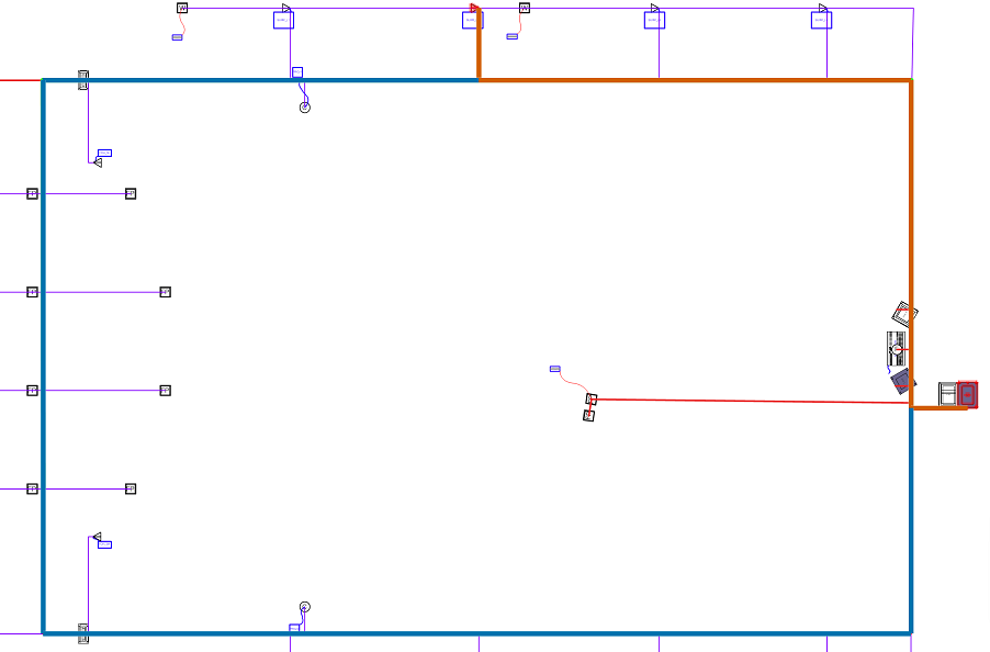
The shortest route is highlighted in orange; an alternative, longer route displays in blue
Click Select Alternative Route.
The Select Route dialog box opens, listing the available routes and their lengths.
Select an alternative route by clicking in the Use column.
If more than one circuit was selected, all of them use the new cable route.
