 Workflow: Cable routing with ConnectCAD
The integration of a schematic systems design with the physical building model progresses in multiple stages.
Schematic plan
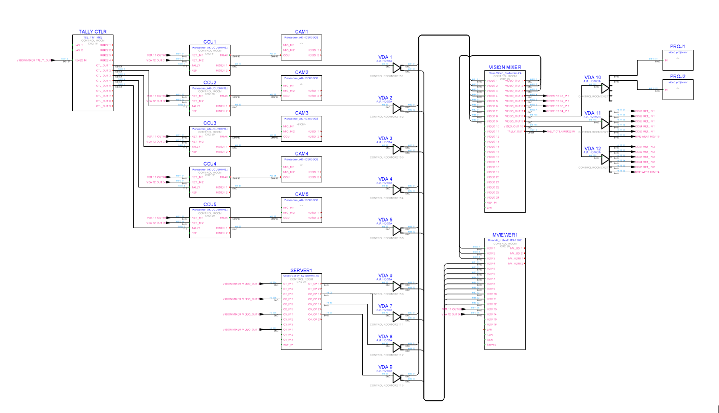
Using the tools in the Schematics palette, lay out the major components of the system, the required connections between them, and the types of cable required for the connections. Only the logical connections and cabling are diagrammed at this point, without considering the actual physical location.
Physical layout
This segment of the workflow has three major components which can operate independently of each other and in no particular order.
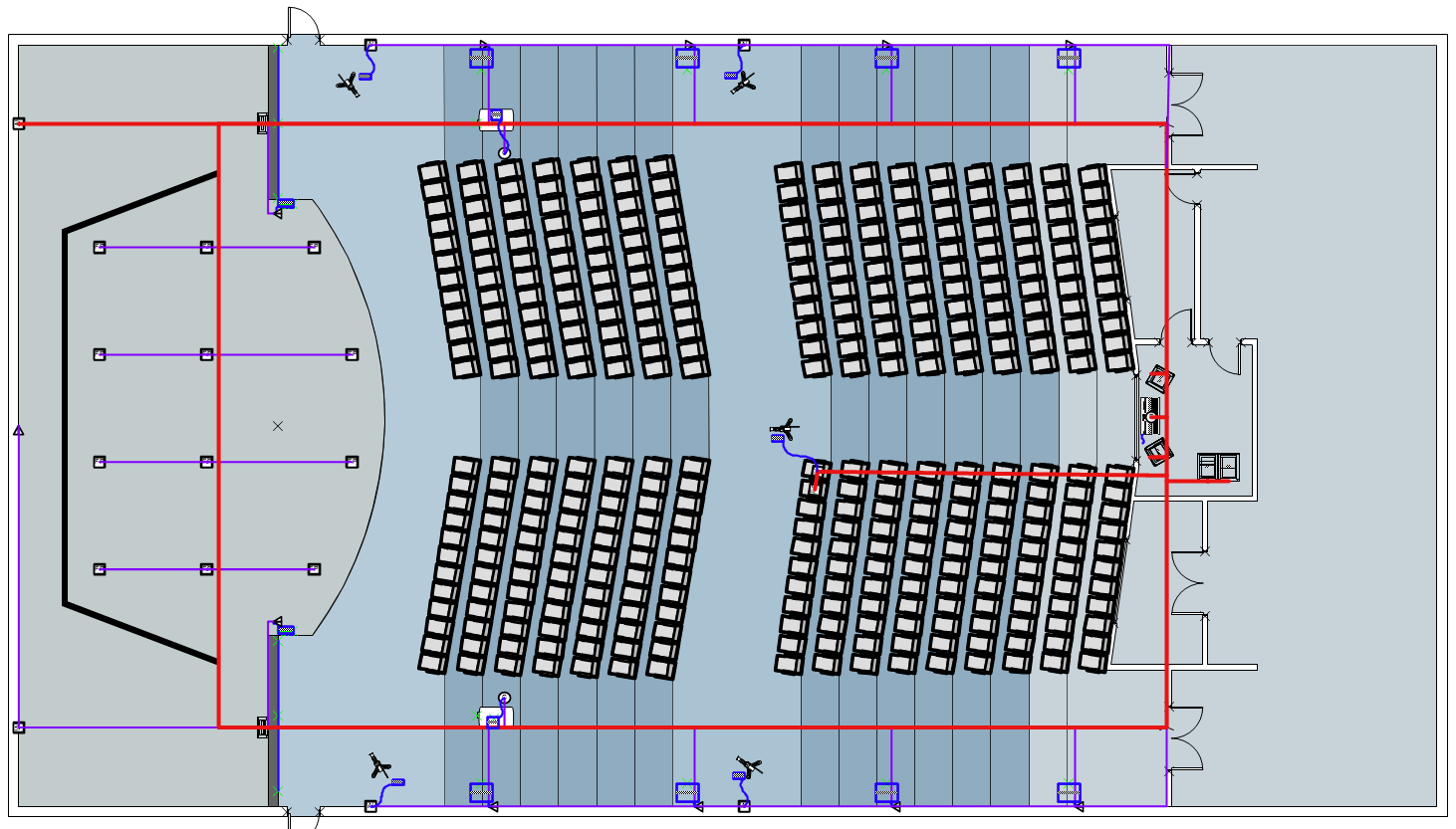
Locate major equipment: Create or obtain, from the architect or project planner, a scaled floor plan or full model of the building or venue.
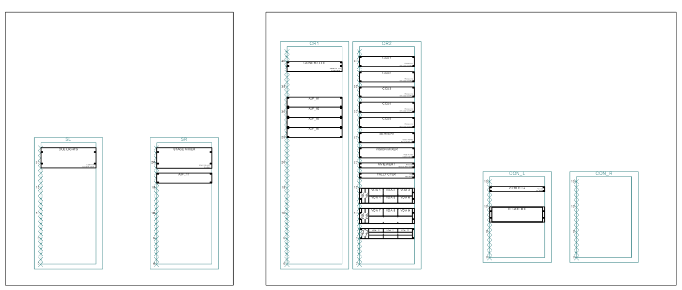
Place the major equipment in the building using the tools in the Event Design tool set and the Equipment Item tool.
Create equipment items automatically with the Create Equipment command; any devices/equipment on the schematic and in layout layers will have corresponding equipment item objects created.
Place or drag an equipment item onto an object from the Event Design tool set to identify it as valid equipment.
Drag the pieces of equipment to the correct location and layers on the floor plan, into 3D equipment racks, and into the model.
Insert drop points: A drop point is the terminus of a cable (where the cable exits). Place drop points in walls, ceilings, and floors as applicable.
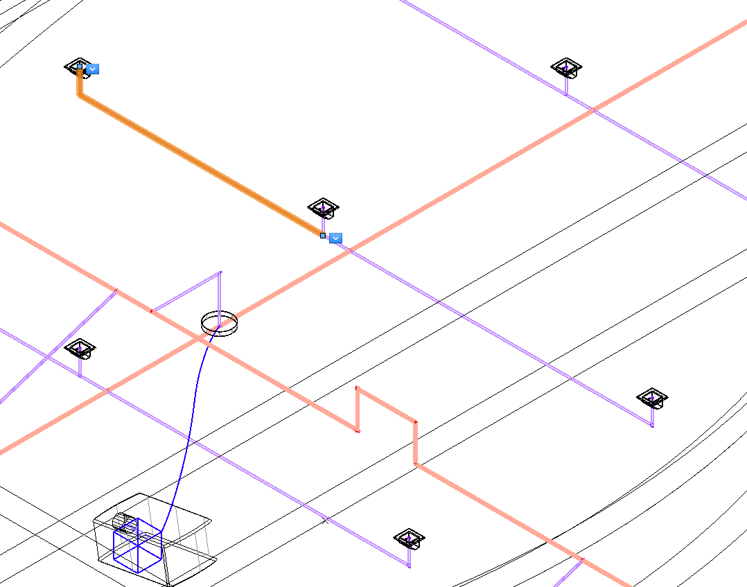
Define 3D cable routing: Use the Cable Route tool to draw networks of cable paths. Cable paths represent the physical routes of ducts and conduits through which cables are routed. The XY mode (horizontal) and the Z mode (vertical) allow creation of cable paths in the proper orientation and elevation. Additional branches (which automatically join and remain connected) can be added to cable paths to create networks of paths.
Pre-cable the model: If the design of the cable routing must begin long before the equipment is selected and the schematic is finalized, use the Edit Cabling tool to pre-cable the conduits to specific drop points with "spare" cables, and then later, this pre-cabling gets used during detailed design to connect the equipment that is finally chosen.
Cable connections
Once physical planning is substantially complete, the following tasks can be completed in any order.
Connect drop points to cable path network: The Cable Route tool associates drop points with the network of cable path objects. In XY Insertion mode, define a polyline path at the selected cable height; the tool attaches to drop points and other cable paths, making any elevation adjustments needed.
Connect equipment items to drop points: Move the equipment item objects to the correct location relative to the drop point. Drag the control point of the equipment to the drop point to make the connection.
You can connect multiple equipment items to a drop point by selecting all of the equipment control points with the Unrestricted Interactive Scaling mode of the Selection tool enabled. Drag the control points towards the drop point.
Use the Analyze Cable Routes command with the Edit Cabling tool to view the assignment of circuits to cable path segments, and, if needed, assign them to alternative routes.
Cable length calculations
The Calculate Cable Lengths command verifies and calculates the cable network connections. It determines the beginning and ending points of circuits across the cable network, and flags errors.
Revisions
Schematic
As the time for the installation nears, finalize the equipment list, taking into account, and substituting where appropriate, new versions of devices and equipment and drawing or updating the circuit connections. Update the physical layouts and requirements by updating the equipment locations, mounting details, and electrical requirements.
Reshaping cable paths
Cable paths can be updated and reshaped using the Reshape tool.
Move the control point vertex of a cable path segment, and the other segments remain connected and reshape themselves accordingly.
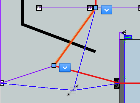
Dragging a cable path segment to reshape the path
If needed, drag the equipment item control point to a new/different drop point to re-assign equipment items, or detach equipment items from an object.
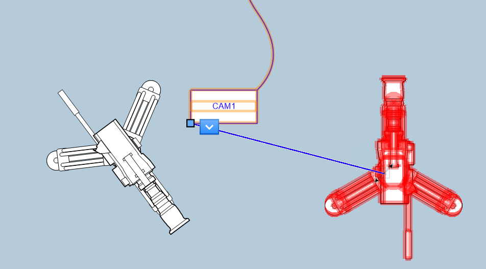
Moving an equipment item designation from the camera on the left to the camera on the right
You can select and reshape the end-vertex of a cable path branch connecting a drop point to another part of the cable path network. The network adds branches automatically.
Analysis and reports
Assign circuits from the schematic to the cable path segments using the Analyze Cable Routes command, and verify any cable path segments for the circuits it contains with the Edit Cabling tool.
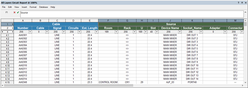
Use the reports described in Creating ConnectCAD reports to get lists of cables/circuits in the cable path, cable lengths, and so on.
The cable outside diameter, combined with the calculated cable length, can give an estimate of the capacity required by a cable path object. Once circuits have been assigned to the cable path segments with the Analyze Cable Routes command, use data visualization to create a capacity heat map for the cable path design. See Creating a new data visualization.
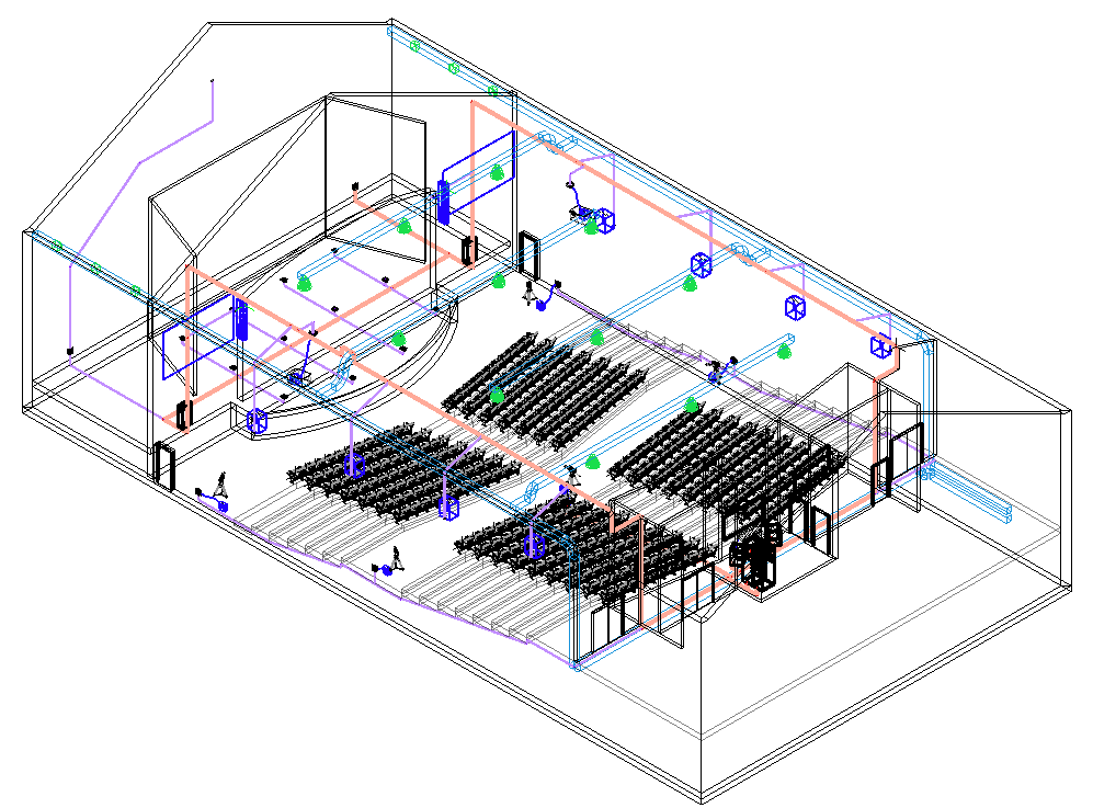
Creating model views
Use sheet layer viewports with Top/Plan and isometric views of cable paths and physical equipment to explicitly show the required runs of cable to the contractors who will be installing the cable containment system or the cabling itself. Keep in mind that the connections represented in the views are cable paths, not individual cables. Data tag content allows easy annotation of these drawings.
Creating cabling sheets and riser diagrams
ConnectCAD can automatically create two additional views of the model: cabling sheets and riser diagrams for conduit installation and cable routing. These views of the model are created as sheet layer viewports.
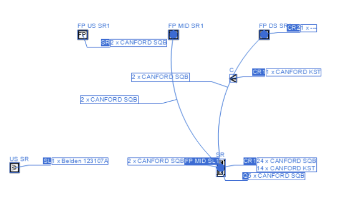
On the cabling sheet, cable runs are indicated as arcs between drop points, or “home runs” to named locations. The runs are annotated with the quantities and types of cables for each run.
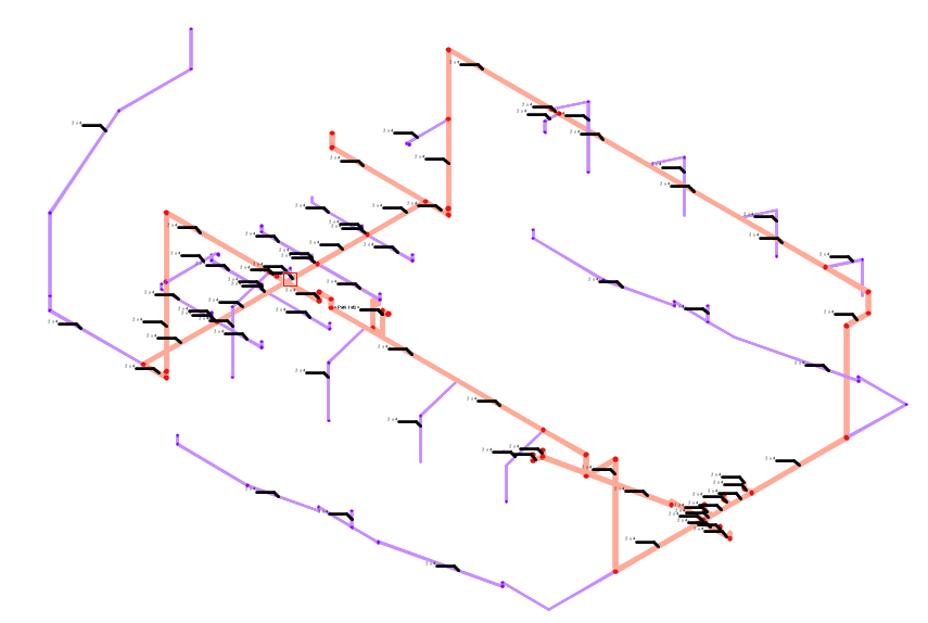
Riser diagrams are maps of the entire cable path system. They show the routes on individual floors and between floors. Routes on a riser diagram are typically annotated by the designer with the suggested size and type of cable containment (conduit, duct, cable tray, etc.).
![]()