 Creating circuits
|
Tool |
Tool set |
|
Connect
|
Schematics |

Circuits can be drawn from an output/IO socket to an input/IO socket, and from an input/IO socket to an output/IO socket.
Each circuit has a source socket and a destination socket. The source is an output or IO socket, and the destination is an input or IO socket. If a circuit is drawn from an input socket to an output socket, the input socket becomes the destination, and the output socket becomes the source. This way, the circuit direction mirrors the signal flow.
To connect sockets:
Click the tool.
Do one of the following:
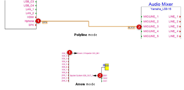
To connect the socket from one device to a socket on another device, click Single Connect mode. Click one of the circuit vertex modes, depending on whether you want the circuit to look like a standard corner vertex polyline, a polyline with rounded or chamfered vertices, or an arrow indicating the direction of the signal flow with a reverse arrow at the destination socket.
To connect multiple sockets from one device to another at one time, click Multi Connect mode. Sockets with the same signal type are connected automatically between two devices. (Alternatively, use the Connect Selected command, which is similar; see Connecting circuits automatically.)
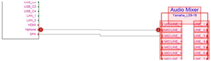
To connect sockets on devices by clicking to create corner, rounded, or chamfered vertices (usually done to route the circuit around other objects), click Polyline, Rounded, or Chamfer mode.
Click Arrow mode to connect sockets that are too far away from each other, or sockets that are on different layers.
Alternatively, convert a custom shape into a generic circuit with the Modify > Create Objects from Shapes command. Customize the circuit later by adding connections and other data.
Click on the source socket.
Draw the circuit or circuits, clicking if necessary to route the circuit around other drawing objects. A preview indicates the circuit’s location, and the Data bar displays the names of the sockets to be connected.
Click on the destination socket to create the circuit.
In Arrow mode, you can switch to a different layer if needed while using the Connect tool. From the Navigation palette, place a check mark to activate the desired layer. Alternatively, use the arrow key shortcut to step through the layers in order: Cmd + up/down arrow (Mac) or Ctrl + up/down arrow (Windows). Connect the circuits. The Connect tool switches back to the original layer after the operation.
In Multi Connect mode, click on the source device and socket type, and then click on the target device and first socket to connect. The entire target device is highlighted, and any eligible connections between the devices are created.
The circuit or circuits are created.
In Single Connect mode, double-click on the next source socket to connect it to the next available socket on the same target device.
Edit the circuit parameters from the Object Info palette; see Editing circuits.
