Hoist properties
Hoist properties can be viewed and edited from the Object Info palette. Some of the parameters are set automatically based on the selected symbol.
To select all hoists in the file that share a common characteristic, right-click on a hoist to edit, and select one of the following commands from the context menu: Select Hoists with the Same Name, Select Hoists with the Same Symbol, Select Hoists with the Same Function, or Select Hoists with the Same Capacity.
Click to show/hide the parameters.Click to show/hide the parameters.
|
Parameter |
Description |
|
Rotation |
Rotates the hoist object, as well as the basic labels |
|
Text Style |
Select a text style from a library or the current file. To use the style defined for the object's class, select <Class Test Style>. To format the text using options on the Text menu, select <Un-Styled>. See Using text styles and Formatting text. To maintain the proper size and arrow location, the measurement label may not use all the specified text style attributes. |
|
General |
|
|
Hoist ID |
Provide a unique identifier for labels and paperwork. If blank, a value is automatically assigned when calculations are run (Braceworks required). |
|
Hoist Name |
Provide an alpha-numeric identifier to display on the hoist. Typically, this is the hoist type. |
|
Position |
Displays the name of the associated rigging object, if the hoist is attached. Optionally, attach this object to a rigging object, or change the rigging object association, by entering the Position Name of the rigging object. Delete the name to break the association. For other methods to attach loads, see Making the attachment. |
|
Geometry |
|
|
High Hook Height |
Determines the location of the upper hook (the fixed end of the hoist that attaches to the lifting structure) by setting the distance from the floor to the hook. The high hook may be located on the motor or on the end of the chain, depending on the Hoist Position. |
|
Low Hook Height |
Determines the location of the lower hook (the end of the hoist that attaches to the structure being lifted) by setting the distance from the floor to the hook. The low hook may be located on the motor or on the end of the chain, depending on the Hoist Position. Adjusting this height also moves any attached loads. |
|
Hook to Hook |
Displays the distance between the high hook and the low hook |
|
Load Trim |
Specifies the height of the load being lifted by the hoist, measured from the floor to the bottom of the load |
|
Trim at Bottom of Truss |
Displays the height of the truss being lifted by the hoist, measured from the floor to the truss bottom edge. When the truss is rotated, the lowest height on the connection point of the truss is shown. |
|
Trim at Top of Truss |
Displays the height of the truss being lifted by the hoist, measured from the floor to the truss top edge. When the truss is rotated, the topmost height on the connection point of the truss is shown. |
|
Low Hook to Load Trim |
Specifies the distance from the bottom of the load to where the low hook attaches to the load. This offset distance accounts for the height of the load and any pick-up device used for the attachment. This field is automatically populated when a Pick-up Symbol is specified. Load Trim + Low Hook to Load Trim = Low Hook Height |
|
Distance Trim Top Truss |
Displays the distance between the top edge of the truss (Trim at Top of Truss) and the top of the hoist (High Hook Height) |
|
Maximum Chain Length |
Displays the maximum chain length available for the hoist |
|
Chain Length |
Enter the chain length needed. If this value exceeds the Maximum Chain Length, a dead hang bridle of the necessary length is automatically inserted. |
|
Pick-up Symbol |
Displays the symbol used to represent the truss pick or sling. The selected symbol determines the Low Hook to Load Trim value. Advanced users can create custom pick-up symbols. Attach the Hoist Attachment record to define the offset between the low hook height of the hoist and the rigging point of the pick-up symbol. You may need to offset the 2D and 3D portions of the symbol for proper rendering. The motor portion of the 3D symbol can be rotated for the desired appearance. |
|
Select Pick-up Symbol |
Opens a Resource Selector to select a pick-up symbol; double-click a resource to activate it |
|
Properties |
|
|
Chain Runners |
Specifies the number of cable supports required on the hoist for the power, audio, and data cables in a moving truss application |
|
Speed |
Indicates the lifting and lowering speed of the hoist motor |
|
Phasing |
Indicates the power supply type required by the hoist (three phase or single phase), for all hoist types except Block & Fall |
|
Voltage |
Indicates the voltage required by the hoist, for all hoist types except Block & Fall |
|
Connector Type |
Select the type of controller connection; this does not apply to Block & Fall hoist types |
|
Notes |
Add a note for informational purposes |
|
Total Weight |
Displays the calculated weight of the hoist (based on the Hoist Weight) and its chain (based on the Chain Weight). This value represents the “dead load” of the hoist. |
|
Hoist Weight |
Indicates the weight of the hoist without the chain. Confirm that this weight is correct for your specific hoist. |
|
Chain Weight |
Indicates the weight of the chain per unit of distance |
|
Distro/Port |
Specifies the connection location on the controller; this does not apply to Block & Fall hoist types |
|
Structural |
|
|
Capacity |
Indicates the maximum allowed total weight for the hoist, for use in calculations (Braceworks required) |
|
High Hook Force |
Indicates the total force applied to the hoist, including the hoist’s “dead load,” or Total Weight |
|
Low Hook Force |
Indicates the total force applied to the hoist, not including the hoist’s “dead load,” or Total Weight |
|
High Hook Weight Equivalent |
Displays the High Hook Force as a weight value, including safety factors. This parameter was formerly known as the Total Point Load. |
|
Low Hook Weight Equivalent |
Displays the Low Hook Force as a weight value, including safety factors |
|
Chain Shorten |
Allows the chain length to be adjusted for calculation purposes (Braceworks required). Enter a positive number to shorten the chain by that value, or a negative number to lengthen the chain by that value. |
|
Cross Section |
Displays the associated cross section for Braceworks structures |
|
Opens the Select Cross Section dialog box, to select or specify the cross section for the hoist chain. Sets: Select a predefined manufacturer cross section from the list, or select <Rigid> to indicate the use of a generic cross section (a generic cross section assumes that the cross section is rigid for all calculations, Braceworks required). For these selections, no further information can be entered since the selected cross section data is used. Select Custom to enter custom cross section data in the rest of the dialog box. Name: Provides a name for the cross section for use in reports. Cross Section Area: Specifies the total area of the cross section. Allowable Force: Sets the maximum allowable force that can be applied to the cross section. Material: Specifies the type of material that the cross section chain consists of; select from the available options. |
|
|
Hoist Position |
Controls whether the motor portion of the hoist is shown in the top or bottom position, or is not shown in the drawing. This setting determines where the “dead load” of the hoist is calculated (Braceworks required). For example, you can reduce the workload on the roof by selecting Hoist Down, placing the dead load of the hoist on its attached truss. When Hoist Up is selected, the hoist’s attached load moves as well. |
|
Reference Point |
|
|
Origin |
Select the hoist origin to use as a location reference, or use the drawing origin as the reference. If the name of the hoist origin changes, you must update the selected Origin. |
|
X/Y |
Displays the X and Y coordinates of the hoist relative to the selected Origin; these coordinates display on the hoist when Show Measurement Label is selected |
|
Show Measurement Label |
Displays the coordinates and the direction relative to the selected Origin |
|
Measurement Label Pos X/Y |
Controls the location of the measurement label, which can also be adjusted with the label control point |
|
Display |
|
|
Show ID label |
Displays a basic label showing the Hoist ID and the High Hook Force, if calculated (Braceworks required). Hoists used with Braceworks receive color-coded label fills to indicate their calculation status; see Displaying and correcting errors. |
|
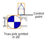
Show pick-up symbol |
Displays the 2D portion of the selected pick-up symbol in 2D and schematic views. Move the control point to reposition the pick-up symbol.
In 3D views, the 3D portion of the symbol displays by default. |
|
Realistic chain (slower) |
Draws each link of the hoist chain in 3D views, which is more realistic but may take longer to display |
|
Pick-up symbol scale |
Scales the pick-up symbol; enter the scale factor |
|
Hoist Symbol Scale |
Scales the hoist symbol; enter the scale factor |
|
Hoist Symbol |
Displays the symbol that represents the hoist |
|
Select Symbol |
Opens a Resource Selector to select a different hoist symbol; double-click a resource to activate it |
|
Opens the Classes dialog box, to specify class naming for the basic hoist labels (the ID label and measurement label), and the hoist chain. This allows the hoist labels and chain to be set to visible, grayed, or invisible. Use the standard class, select a class from the list of classes present in the drawing, or create a new class. Use Standard Classes: Sets the class name for the label to the standard. ID Label: Specifies the class name standard to apply to the hoist label. Measurement Label: Specifies the class name standard to apply to the measurement label. Chain: Specifies the class name standard to apply to the chain. |