 Placing irrigation system components
|
Tool |
Tool set |
|
System Component
|
Irrigation |
A variety of additional objects may be needed to make the irrigation design complete. These electrical and mechanical devices can be added to the drawing with the System Component tool.
The predefined objects that can be placed include: auto-fill device, backflow preventer, blow out connection, environmental sensor/station, filter, flow sensor, hose bib/faucet, pressure regulator, quick coupler, valve box/enclosure, water meter, and other. You can also place a generic system component with parameters that can be specified after placement.
A system component added to a pipe splits the existing pipe in two.
To place a system component on the drawing:
Click the tool.
Click System Component from the Tool bar to select a resource from the Resource Selector. Select from one of the manufacturer libraries, or select a custom resource from Generic.vwx and set its properties after placement.
Click Preferences to open the object properties dialog box opens and specify the default system component settings; in particular, specify the component type and symbol to use.
Click to show/hide the parameters.Click to show/hide the parameters.
|
Parameter |
Description |
|
Component Name |
Names the object, which is useful for labels, irrigation schedules, and other worksheets |
|
Note |
Adds a note about the object, which is useful for labels, irrigation schedules, and other worksheets, and also for making notes when saving red symbol definitions |
|
Graphics |
|
|
Symbol Name |
Displays the name of the symbol used to represent the component; <default symbol> indicates that the default component symbol is used |
|
Replace Symbol |
Selects a component symbol; choose the symbol from the appropriate category |
|
Symbol Scale |
Scales the symbol with respect to the layer scale by the specified scale factor; a factor of less than one decreases the size of the symbol, while a factor of more than one increases its size |
|
Show Input Pressure |
Places a pressure label on the drawing |
|
Show Flow |
Places a flow rate label on the drawing |
Click once to place the system component. If placing the component over an existing pipe or irrigation pipe network, the connecting pipe is highlighted and the component is automatically connected to the network.
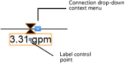
Adjust the location of the component labels by dragging the label control point.

The system component properties can be edited from the Object Info palette. Available parameters depend on the system component type.
Click to show/hide the parameters.Click to show/hide the parameters.
|
Parameter |
Description |
|
Save System Component |
Saves the selected component as a red symbol definition in the active file; this would typically be done for a custom component |
|
Component Name |
Names the object, which is useful for labels, irrigation schedules, and other worksheets |
|
Note |
Adds a note about the object, which is useful for labels, irrigation schedules, and other worksheets, and also for making notes when saving red symbol definitions |
|
Component Type |
Indicates the type of system component |
|
Display in Drawing |
Select either Design Information or Calculated Information to affect the display of all calculated values and coverage zones in the drawing; see Concept: Design and calculation parameters for irrigation |
|
Design Information |
|
|
Input Pressure |
Specifies the design input pressure for the system component |
|
Output Pressure |
Displays the design output pressure for the system component |
|
Flow |
Indicates the flow rate through the component when the downstream outlets operate as specified |
|
Pressure Loss |
Enter the system component’s designed pressure loss; when the component is connected to the system, this pressure loss is factored into calculations |
|
Calculated Information |
|
|
Input Pressure/ Output Pressure/ Flow |
Displays the calculated input and output pressure, and flow rate based on the entire system’s calculated parameters |
|
Pressure Loss |
Displays the pressure loss when the component is connected to the system |
|
Catalog Data |
|
|
Get From Catalog |
Opens the Catalog dialog box, for obtaining catalog data for the selected object (typically, this is for adding catalog data to a custom object that has none); see Concept: Using the irrigation catalog |
|
Data |
Displays the catalog data; available catalog parameters vary, depending on the type of system component |
|
Comment/Comment 1–4 |
Additional comment fields allow further specifications/information to be added to the catalog data |
|
Modify Catalog Data |
Makes the data fields editable; modify the data, which can then be saved as a custom entry in the catalog |
|
Save In Catalog |
Opens the Catalog Item Edit dialog box, where the custom data can be further edited and then added to the catalog |
|
Graphics |
|
|
Symbol Name |
Displays the name of the symbol used to represent the component; <default symbol> indicates that the default component symbol is used |
|
Replace Symbol |
Selects a component symbol; choose the symbol from the appropriate category. |
|
Symbol Scale |
Scales the symbol with respect to the layer scale by the specified scale factor; a factor of less than one decreases the size of the symbol, while a factor of more than one increases its size |
|
Attach Tag/Label |
Automatically attaches a Tag/Label object to the object. The last selected tag/label for the object type is applied; click the tag/label to edit its properties (see Adding labels to irrigation objects). |
|
Show Input Pressure |
Places a pressure label on the drawing |
|
Show Flow |
Places a flow rate label on the drawing |
