 Placing valves
|
Tool |
Tool set |
|
Valve
|
Irrigation |
The Valve tool places an irrigation valve with parameters from a selected manufacturer or a custom valve with parameters that can be specified after placement. Various valves provide a wide array of functions in an irrigation system. Depending on the type of valve, different parameters are available.
Control or zone valves connect the system’s main line to the associated lateral lines and downstream outlets.
Master valves connect the entire irrigation system to the water source near the point of connection.
Zone kit valves consist of valve, filter, and regulator in preassembled kits.
A valve added to a pipe splits the existing pipe in two.
To place valves on the drawing:
Click the tool.
Click Valve from the Tool bar to select a resource from the Resource Selector. Select from one of the manufacturer libraries, or select the custom valve from Custom.vwx and set its properties after placement.
Click once to place the valve. If placing the valve over an existing pipe or irrigation pipe network, the connecting pipe is highlighted and the valve is automatically connected to the network.
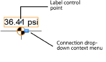
Adjust the location of the valve labels by dragging the label control point.

The valve parameters can be edited from the Object Info palette. Available parameters depend on the valve type.
Click to show/hide the parameters.Click to show/hide the parameters.
|
Parameter |
Description |
|
Save Valve |
Saves the selected valve as a red symbol definition in the active file; this would typically be done for a custom valve, or a valve with modified catalog data |
|
Valve Name |
Names the object, which is useful for labels, irrigation schedules, and other worksheets |
|
Note |
Adds a note about the object, which is useful for labels, irrigation schedules, and other worksheets, and also for making notes when saving red symbol definitions |
|
Valve Type |
Indicates the type of valve |
|
Zone ID |
For valves that control a zone, provide an identifier label for informational purposes |
|
Display in Drawing |
Select either Design Information or Calculated Information to affect the display of all calculated values and coverage zones in the drawing; see Concept: Design and calculation parameters for irrigation |
|
Design Information |
|
|
Input Pressure |
Specifies the designed input pressure that reaches the valve |
|
Output Pressure |
Indicates the designed pressure that exits the valve |
|
Pressure Loss |
Specifies any pressure loss caused by the valve |
|
Flow |
Indicates the flow rate through the valve when the outlets in its zone operate as specified |
|
Calculated Information |
|
|
Input Pressure |
Displays the input pressure expected to reach the valve when it is connected to a network |
|
Output Pressure |
Displays the pressure expected to exit the valve Output Pressure = Input Pressure - Pressure Loss |
|
Pressure Loss |
Displays the pressure loss that occurs within the valve |
|
Flow |
Indicates the flow rate through the valve as a result of the outlets in its zone operating at their received pressure |
|
Catalog Data |
|
|
Get From Catalog |
Opens the Catalog dialog box, for obtaining catalog data for the selected object (typically, this is for adding catalog data to a custom object that has none). See Concept: Using the irrigation catalog. |
|
Data |
Displays the catalog data |
|
Decoder (2-wire) (control, master, zone kit) |
Specifies the presence of an electronic 2-wire controller component |
|
Pressure Regulation (control, master, zone kit) |
Indicates the use of a pressure regulator; specify the regulated pressure, which prevents the design and calculated Output Pressure value from rising above the regulated limit. Zone Kit valves always have pressure regulation. |
|
Regulated Pressure (control, master, zone kit) |
Sets the regulated pressure limit |
|
Flow Control (control, master, zone kit) |
Indicates the presence of a flow control limiter |
|
Non-potable (control, master, zone kit) |
Indicates that the valve carries non-potable water |
|
Comment 1–4 (isolation, shut off, air relief, vent, check drain, other) |
Additional comment fields allow further specifications/information to be added to the catalog data |
|
Modify Catalog Data |
Makes the data fields editable; modify the data, which can then be saved as a custom entry in the catalog |
|
Save In Catalog |
Opens the Catalog Item Edit dialog box, where the custom data can be further edited and then added to the catalog |
|
Graphics |
|
|
Symbol Name |
Displays the name of the symbol used to represent the valve |
|
Replace Symbol |
Selects a valve symbol; choose the symbol from the appropriate category |
|
Symbol Scale |
Scales the symbol with respect to the layer scale by the specified scale factor; a factor of less than one decreases the size of the symbol, while a factor of more than one increases its size |
|
Attach Tag/Label |
Automatically attaches a Tag/Label object to the object. The last selected tag/label for the object type is applied; click the tag/label to edit its properties (see Adding labels to irrigation objects). |
|
Show Input Pressure |
Places a pressure label on the drawing |
|
Show Flow |
Places a flow rate label on the drawing |
