 Plant settings
By using plug-in object styles, you can create plants with a combination of parameters that are determined by style or by instance. Style parameters have a fixed value established by the style; instance parameters can be set independently for each instance of the object in the drawing; see Concept: Plug-in object styles and Creating plug-in object styles.
If plant data were obtained from the plant catalog or database, those are displayed. Values and settings entered on the Plant Style or Plant Preferences dialog boxes become the default for the plant.
The parameters in the Plant Preferences, Plant Settings, and Edit Plant Style dialog boxes are identical, except for the controls related to selecting or creating a style.
Click to show/hide the parameters.Click to show/hide the parameters.
|
Parameter |
Description |
|
Use Style (Plant Preferences and Plant Settings dialog boxes) |
Select a style from the Resource Selector |
|
Duplicate Style (Plant Preferences and Plant Settings dialog boxes) |
Opens the Edit Plant Style dialog box to create a duplicate plant style based on the selected plant's style |
|
Plant Style Name (Edit Plant Style dialog box) |
Displays the plant style’s name as specified in the Name Formula; this name also displays in the Resource Manager and Object Info palette |
|
Name Formula (Edit Plant Style dialog box) |
Enter a name for the plant style and select a prefix and suffix to be appended to the name, if desired. To create a new plant style, enter a new name. To edit the current plant style, leave the name unchanged. |
|
Previews |
Dynamically previews the plant appearance, showing how it will appear when added to the drawing |
|
Top/Plan Preview |
Displays the 2D component of the plant symbol |
|
3D Preview |
Displays the 3D component of the plant symbol, if one has been added to the symbol definition (image props, such as those provided by xFrog, can be used as 3D plant geometry) |
Plant settings: Species and Data pane
Click to show/hide the parametersClick to show/hide the parameters
|
Parameter |
Description |
|
Species |
|
|
Latin Name |
Specifies the plant genus and species (botanical name) |
|
Common Name |
Specifies the plant common name or names |
|
Plant Catalog (Edit Plant Syle dialog box only) |
Depending on the selection made in the Choose Plant Data Source dialog box (see Selecting the plant data source), plant data can be either associated with plants from plant catalogs or from the plant database. If plant catalogs are the source, the Select Plant Data dialog box opens. Select the plant to associate from the list. The plant data from the catalog is imported. See Using plant catalogs for additional information. If the plant database is the source, the plant database opens, if it is not already open (this may take several seconds). A dialog box in Vectorworks indicates that Vectorworks is waiting for you to select data from the plant database for the plant style. If you change your mind about obtaining the plant style data from the plant database, click Cancel Data Acquisition. Select a plant record from the plant database as described in Searching for plants. Once the correct plant has been located, from the plant database, select Vectorworks > Use Currently Selected Record. This associates the plant database record with the plant style. From either source, once the plant data has been associated with the plant style, the catalog or database information updates the appropriate plant style parameters, if specified when the plant data source was selected. |
|
Data |
|
|
Plant/TagID |
Identifies the plant with a unique code; this code appears in the plant list and on ID tags, if selected (see Plant ID codes for the definition of common code categories) |
|
Scheduled Size |
Indicates the plant caliper or container size; displays in the Plant List worksheet |
|
Quantity Type |
Determines the Quantity value for the attached Plant record, primarily for the purpose of calculating plant worksheets with the plant cost per count or the cost per area. The Quantity Type can be defined by unit count, dripline area, or border area: Count: Counts the number of plants within an array of plants. Dripline area: Considers the area, in current document units, of the drip line polygon (the tight bounding polygon around the plants). Boundary area: Considers the area, in current document units, of the plant array polygon as drawn. |
|
Price Code (SKU) |
Specifies the price code entry in Stock Keeping Units (SKU) |
|
Price |
Indicate the plant cost per unit of quantity; the plant cost and quantity are reflected in the Extended Price calculation in the Plant List worksheet |
|
Planting/Nursery Schedule Comments |
Specifies default comments about the plant that display in the Plant List worksheet |
Plant settings: Size and Spacing pane
Click to show/hide the parameters.Click to show/hide the parameters.
|
Parameter |
Description |
|
Size |
|
|
Spread |
Specifies the default plant spread diameter (the maximum width of the mature plant, as drawn) for both single and multiple plant placement |
|
Height |
Sets the default height of the typical mature plant at insertion |
|
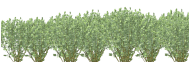
Hedge Rows |
Specifies the number of hedge rows to create when Hedge mode is enabled |
|
Hedge Mode |
Select the arrangement of hedge rows when Hedge mode is enabled |
|
Space and Array Modes Options |
|
|
Spacing by |
For the Poly-Vertex Placement, Poly-Edge Spaced, Rectangular Array, and Triangular Array insertion modes, sets the default spacing between plants at insertion; select Distance, Rate, or Coverage |
|
Distance |
Sets the horizontal distance between plants (Spacing) and between vertical rows of plant arrays (Row Spacing). Fixed Spacing: Places plants at the specified distance Best Fit: Places plants at the start and end of the line or array, and then distributes the plants evenly at the specified distance Count: Distributes the specified number of plants evenly along the line or within the array Same as Spacing: Sets the Row Spacing to be the same as the Spacing selection |
|
Rate (rectangular and triangular array) |
Calculates the plant spacing, for arrays only, based on the plant area. Specify the rate: Plants per square unit: Spaces the plants according to the set density, with the square unit specified in the document settings Unit on center: Spaces the plants from center to center, according to the length units specified in the document settings |
|
Coverage |
Calculates the plant spacing based on the actual plant area and Spread values, and places them according to the set Percentage. A value of 100%, for example, indicates full coverage, with plants spaced according to the Spread. |
Plant settings: Insertion Options pane
Click to show/hide the parameters.Click to show/hide the parameters.
|
Parameter |
Description |
|
Mode (Plant Preferences and Plant Settings dialog boxes only) |
Select the default placement mode for this plant |
|
Include on plant list |
Includes this plant on a plant list |
Plant settings: Graphics pane
The plant graphics, which are defined by the plant style, can easily be created from a symbol, from an existing plant, from automatically generated 3D geometry, or from an image.
Plant graphics can also be created from 2D and optionally 3D drawing objects, including xFrog plant images, image props, and Laubwerk plants. Once the plant has been created, edit the symbol components as necessary; see Editing symbol definitions.
Click to show/hide the parameters.Click to show/hide the parameters.
|
Parameter |
Description |
|
Edit Current Graphics |
Closes the Edit Plant Style dialog box to set all parameters, and opens Object editing mode to edit the 2D or 3D graphics for the plant symbol. Alternatively, right-click on a plant instance that uses the style, and select Edit from the context menu, and then click 2D Graphics or 3D Graphics. Editing the plant attributes from an instance edits the plant style and affects all plants that use that style. |
|
Laubwerk Geometry |
Opens the Laubwerk Plant Catalog dialog box, to select a Laubwerk plant and specify its seasonal and appearance settings. See Adding 3D plants from Laubwerk. |
|
Obtains the 2D or 3D plant geometry from a symbol in the file or from a library. The Copy From Symbol 2D or Copy From Symbol 3D dialog box opens. Click the plant selector. From the Resource Selector, double-click a plant resource to activate it, and then specify whether to resize the diameter and/or height of the symbol geometry. |
|
|
Generate |
Generates 3D plant geometry when the 3D representation of the symbol used to create the plant is not suitable; see Generating 3D plant geometry from a shape |
|
Generates 3D plant geometry when the 3D representation of the image used to create the plant is not suitable. The Create From Image dialog box opens. Click the image selector. From the Resource Selector, double-click an image resource to activate it, and then specify whether the diameter and/or height of the plant geometry image. |
Generating 3D plant geometry from a shape
When generating plant geometry from another symbol, the 3D representation may not be available, or not suitable for the new plant. 3D geometry can be automatically generated, creating a suitable representation of the plant style in 3D views.
On the plant settings Graphics pane, Plant settings: Graphics pane, click Generate. The Generate 3D Plant Geometry dialog box opens.
Click to show/hide the parameters.Click to show/hide the parameters.
|
Parameter |
Description |
|
Preview |
Displays a preview of the 3D geometry to be generated. Select a View for the preview. |
|
Parameters |
|
|
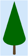
Canopy Shape |
Select a general shape for the tree canopy; the preview dynamically displays the shape |
|
Canopy Spread |
Sets the diameter of the canopy shape at its widest point |
|
First Branch Height |
Sets the height where the trunk ends and the canopy starts |
|
Canopy Height |
Specifies the height of the canopy, not including the trunk |
|
Item Height |
Specifies the total height of the canopy including the trunk |
Plant settings: Appearance pane
A document preference makes it easy to give plans a uniform appearance by applying a document-wide shadow style to all plants and massing models in a drawing (see Document preferences: Plan Shadows tab), but this document preference can be overridden for plant instances or plant styles. The outline, massing, and shadow parameters can be toggled on or off for all plants in a document by selecting View > Show > Show or Hide Plant Details.
The massing, outline, and shadow effects display in Top/Plan view only; plant shadows do not display in worksheet images.
Click to show/hide the parameters.Click to show/hide the parameters.
|
Parameter |
Description |
|
Plan View Effects |
|
|
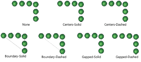
Polygon Display |
For multiple plant placements, changes the display of the boundary or center polygon defining the plant cluster shape.
|
|
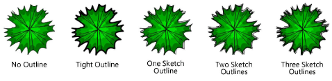
Mass Outline |
Select a plant outline style
The outline’s pen attributes can be changed for selected plant objects in the Attributes palette. |
|
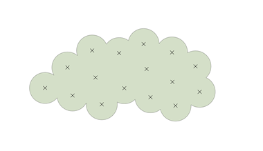
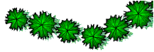
Apply fill across plant grouping |
A continuous outline is created around overlapping plants, and internal details are hidden. The 2D appearance of the massed group is controlled by the back polygon in the plant symbol group, so massing could cause the plant to display without a fill color. (An alternative way of hiding plant details is to use the Plant-Components classes to control the visibility of elements within the plant symbol.)
Keep in mind the following points about this setting: Open areas in a plant style's background fill cannot be filled. Plants that contain bitmap images cannot be massed. Hedges only fill when inserted with Poly-Edge Spaced mode. |
|
Show shadow |
Displays shadow effects in Top/Plan view only. Select whether to use the plan shadows settings in document preferences or custom shadow settings, and click the appropriate button to confirm or adjust the settings; see Document preferences: Plan Shadows tab or Plant shadow settings. |
|
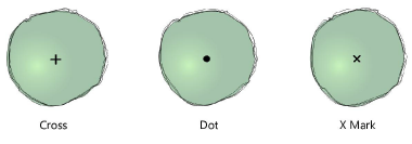
Tick Mark |
|
|
Style |
Select a tick mark (plant center mark) style
|
|
Size |
Specifies the tick mark size |
|
Class |
To control appearance and visibility, select a class for the tick mark from the list of classes present in the drawing, or create a new class. Select <Plant Class> to place the tick mark in the same class as the plant object. |
|
Rotation and Variation |
|
|
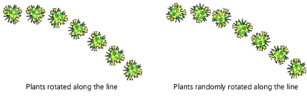
Plant Rotation |
For multi-plant placements, orients the plants in the horizontal direction, rotates the plants along the line created by the drawn polygon, or rotates the plants randomly, creating a more natural appearance |
|
Plant Diameter Variation |
Keeps the plants at a fixed size, or randomly varies the plant diameter according to the specified percentage of variation
|
|
Plant Height Variation |
Keeps the plants at a fixed height, or randomly varies the plant heights according to the specified percentage of variation
|
Plant settings: Root Zones pane
Click to show/hide the parameters.Click to show/hide the parameters.
|
Parameter |
Description |
|
Root Ball |
The root ball is the main mass of the plant's roots |
|
Show |
Select which view displays the root ball: 2D Only 3D Only 2D and 3D To hide the root ball, select Bare Root (None). |
|
Shape |
Select the 3D shape of the root ball |
|
Size |
Select the size of the root ball. The values available depend on the selected Shape. To add, edit, or delete custom sizes, see Adding, editing, or deleting custom root ball sizes. |
|
Class |
To control appearance and visibility, select a class from the list of classes present in the drawing, or create a new class. Select <Plant Class> to place the root ball in the same class as the plant object. |
|
Attributes by class |
Select to set all 2D root ball attributes by class. If this parameter is selected, Line Style and Line Color are disabled. |
|
Line Style |
Select the line style of the root ball |
|
Line Color |
Select the line color of the root ball |
|
Planting Excavation |
The planting excavation is the area that needs to be dug out for the root ball to be planted |
|
Show |
Select which view displays the planting excavation: 2D Only 3D Only 2D and 3D To hide the planting excavation, select None. |
|
Diameter |
Select the planting excavation diameter. To specify a custom diameter, select Custom and specify a Value. The diameter must be large enough to fit the root ball shape. |
|
Value |
Displays the value of the planting excavation Diameter |
|
Depth |
Select the planting excavation depth. To specify a custom depth, select Custom and specify a Value. |
|
Value |
Displays the value of the planting excavation Depth |
|
Class |
To control appearance and visibility, select a class from the list of classes present in the drawing, or create a new class. Select <Plant Class> to place the excavation in the same class as the plant object. |
|
Attributes by class |
Select to set all 2D planting excavation attributes by class. If this parameter is selected, Line Style and Line Color are disabled. |
|
Line Style |
Select the line style of the planting excavation |
|
Line Color |
Select the line color of the planting excavation |
Adding, editing, or deleting custom root ball sizes
To add, edit, or delete root ball sizes:
On the Root Ball tab, select a root ball Shape. The selected shape determines the values available in the Size list.
Select Edit Custom Items from the Size list.
The Edit Custom Items dialog box opens.
Do one of the following:
To add an item, click Add; the Add Custom Dimensions dialog box opens. Specify the Name and dimensions, and click OK. The item is added to the Edit Custom Items dialog box.
To edit an item, select the item and click Edit; the Edit Custom Dimensions dialog box opens. Edit the Name and/or one or more dimensions, and click OK. The edited item is displayed in the Edit Custom Items dialog box.
To delete an item, select the item and click Delete.
Click OK.
If you added or edited an item, the item is displayed in the Size list. If you deleted an item, the item is removed from the Size list.
Plant settings: Tag pane
The Data Tag tool provides more flexible options for tagging plants; see Adding data tags and labels.
To create a custom plant tag using the plant object's tag capabilities, see Creating a custom plant tag. After creation, the plant tag’s appearance can also be modified via the Object Info palette, tag class settings, and the control point locations on the drawing (see Plant tag appearance).
Click to show/hide the parameters.Click to show/hide the parameters.
|
Parameter |
Description |
|
Display |
Select whether to display a plant tag to the right or left of the leader line, in the center of the plant or group of plants, or to display no tag. A Center tag has no shoulder or leader; set the X/Y Offset for Center tags, if needed. |
|
Class |
To control appearance and visibility, select a class from the list of classes present in the drawing, or create a new class |
|
Approach Angle |
Specifies the angle of the leader line, from 0 to 360°. Setting the same angle for several selected plants aligns their leader lines, for an attractive planting plan (see Aligning and distributing leader lines). |
|
Shoulder Angle |
When a tag shoulder line is enabled, sets the angle of the shoulder line and, if selected, tag display, from 0 to 360°. To display the plant tag to the left, specify an angle greater than 90 or less than 270 degrees. To display the plant tag to the right, specify an angle less than 90 or greater than 270 degrees. Setting the same angle for several selected plants aligns their shoulder lines, for an attractive planting plan. |
|
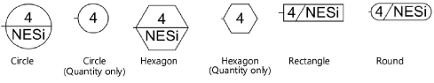
Bubble |
Specifies the bubble style, if any, for displaying quantity or optionally, Plant ID, with the plant tag
|
|
Top/Center/Bottom |
The custom tags present in the drawing and the predefined plant record field combinations for tags are listed. Specify the information to display on each level of the plant tag. For the center level, select Continuation Line to continue the shoulder as a dividing line between the top and bottom tag information. Alternatively, select Set Custom Tag to define a custom plant tag (see Creating a custom plant tag). |
|
Enable tag shoulder line |
Adds a shoulder line to the leader line; adjust the shoulder angle with the shoulder control point, or by entering a tag Shoulder Angle |
|
Snap tag to plant centers |
Snaps the end of the leader line to the center of the plant; deselect to adjust the endpoint location manually |
|
Display tag line marker |
Displays a marker at the end of the leader line; specify the marker to use by editing the plant tag class (see Setting class properties) |
|
Image Size |
Sets the size of any images included in a custom plant tag |
Plant settings: More Data pane
Plant data parameters that are not available on another pane in the dialog box are listed on the More Data pane.
Click to show/hide the parameters.Click to show/hide the parameters.
|
Parameter |
Description |
|
The list of visible fields |
List of plant data parameters and their values, the list can be customized for each plant |
|
Fields Visibility |
Opens the Fields Visibility dialog box; click in the Show column to place a check mark beside fields to include in the list for this plant |
|
Plant Catalog (Edit Plant Syle dialog box only) |
Depending on the selection made in the Choose Plant Data Source dialog box (Selecting the plant data source, plant data can be either associated with plants from plant catalogs or from the plant database. If plant catalogs are the source, the Select Plant Data dialog box opens. Select the plant to associate from the list. The plant data from the catalog is imported. See Using plant catalogs for additional information. If the plant database is the source, the plant database opens, if it is not already open (this may take several seconds). A dialog box in Vectorworks indicates that Vectorworks is waiting for you to select data from the plant database for the plant style. If you change your mind about obtaining the plant style data from the plant database, click Cancel Data Acquisition. Select a plant record from the plant database as described in Searching for plants. Once the correct plant has been located, from the plant database, select Vectorworks > Use Currently Selected Record. This associates the plant database record with the plant style. From either source, once the plant data has been associated with the plant style, the catalog or database information updates the appropriate plant style parameters, if specified when the plant data source was selected. |
|
Field |
Click an item in the list, and its Value displays; click Edit to change the value |
As described in Concept: Plant style and plant data integration, if either Update the Plant catalog with Vectorworks Plant style changes or Update the Plant Database with Vectorworks Plant style changes is selected in the Choose Plant Data Source dialog box, the associated plant catalog (or plant database) automatically updates with any changes made on the More Data pane.
If you are using a plant database file from a version of Vectorworks prior to 2018, the synchronization of images between the plant style and the plant database cannot occur even when using the Migration Manager during the version update, because the older plant database file does not include the new functionality. To fix this issue, export the records in the plant database with the File > Export Records plant database command. Then import the records back into the plant database with the File > Import Records plant database command.
Setting plant data images
Up to four plant images can be selected from the More Data pane. The images can be synchronized with the images in the plant catalog or plant database; see Accessing the plant catalogs or Editing plant records. The fourth option, Custom Image, is not populated by default in the plant database, so it is useful for including an additional graphic in the plant style.
Other image sources, besides those from the plant catalog or database, can be specified from the More Data pane. If not using plant images from the plant style or the plant catalog/database, prepare image files or create/locate a suitable image resource.
To set the plant data image source:
In the list of fields, scroll to the Image Plant Form, Image Detail, Image Misc, and Custom Image parameters.
Click on each one to set its image source. Set Image becomes available; click to specify the image for tag display.
The Set Plant Data Image dialog box opens. Specify the location of the plant image.
Click to show/hide the parameters.Click to show/hide the parameters.
|
Parameter |
Description |
|
Plant Top/Plan Preview |
Uses the plant style image specified for the Top/Plan view. This method of displaying plant images is useful with a plant key. |
|
Plant 3D Preview |
Uses the plant style image specified for 3D views |
|
Import an External File |
Uses an imported image file; click Browse to select the file to import |
|
Image Resource |
Uses an image resource. From the Resource Selector, select an image resource; double-click a resource to activate it. |
|
Plant Image |
Uses the image that was specified for the plant within the plant catalog or database |
|
Remove Image |
If an image source had previously been specified, removes the image. <not set> displays in the Value column of the More Data pane for the item, and no image displays in any associated custom plant tag. The image is also removed from the associated plant catalog or database, when updating is enabled. |
When an image source has been specified, <image> displays in the Value column of the More Data pane. The plant images are synchronized with the plant catalog or database. For this reason, the selection may change to Plant Image regardless of the original selection. For example, if you import an external file for the Image Detail, the plant catalog or database is updated with this image for the Detail Image. In the Set Plant Data Image dialog box, the setting switches to Plant Image since the image now originates from the catalog or database.
To prevent image and plant data synchronization between the associated plant catalog/database and the plant style, deselect either Update the Plant catalog with Vectorworks Plant style changes or Update the Plant Database with Vectorworks Plant style changes (see Selecting the plant data source).
Display images in the drawing within plant tags by Creating a custom plant tag, and add them to worksheets by Inserting images in worksheet cells.
